Facebook
 Google
 GitHub
 Linkedin
A Primer on Digital Pulse Amplitude Modulation
An encoding technique used for digital communication, pulse amplitude modulation (PAM) converts a discrete-time signal into a variable-amplitude continuous-time signal that is suitable for high-speed wired communication systems.
Engineers often face scenarios where information must be transferred through a medium incompatible with the information in its original state. A classic example is audio, where speech or music can be represented by a sinusoidal voltage signal comprising frequencies extending from about 50 Hz to 15 kHz. In theory, this sinusoidal waveform could be delivered to an antenna and broadcast over the air as electromagnetic radiation (EMR). In practice, however, these frequencies are too low for effective wireless communication. Thus, the available medium (i.e., air) does not allow us to directly transmit the information of interest.
The solution is to transmit the information indirectly by encoding the information into a separate signal and then decoding the information at the receiving end of the communication channel. This is what we call modulation.
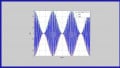
In traditional amplitude modulation (AM), the amplitude of a sinusoidal carrier wave varies continuously according to the amplitude of a baseband information signal (Figure 1).
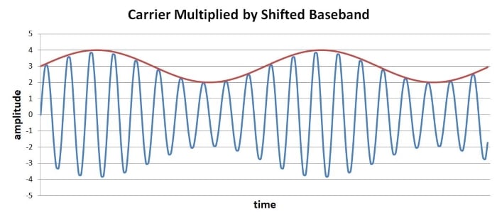
Figure 1. Example waveform showing the carrier multiplied by the shifted baseband.
As shown in Figure 1, amplitude modulation is achieved by shifting the baseband signal so as to eliminate the negative voltage swing and then multiplying the unmodulated carrier wave by the shifted baseband. On the other hand, digital pulse amplitude modulation (PAM) is one method of adapting conventional amplitude modulation to the task of transmitting discrete rather than analog information.
Digital Pulse Amplitude Modulation Basics
In digital PAM, a stream of digital data is encoded into a sequence of “pulses” by translating binary values into amplitude levels. This converts a discrete-time signal into a continuous-time signal, allowing us to reduce the bandwidth required for successful transmission and create a waveform that is well-adapted to long-distance wired communication.
The term “pulse” can be confusing here because it doesn’t necessarily mean “one half cycle of a square wave.” Rather, the pulse is some waveform of fixed duration, and this waveform could be a typical rectangular pulse or something very different, such as a sinusoid. To generate a PAM baseband signal, we transform digital data into amplitude multipliers and apply those multipliers to the pulses. In his lecture slides on digital PAM, Professor Brian Evans uses a truncated raised-cosine waveform as the pulse signal, and he provides the following plot of a PAM baseband signal:
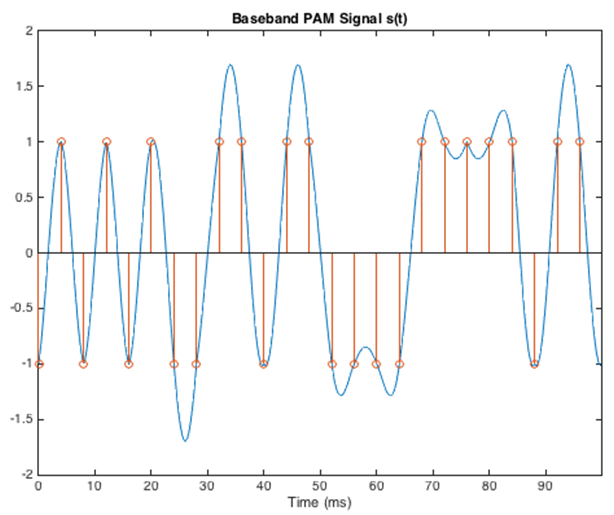
Figure 2. Example plot of a PAM baseband signal. Image used courtesy of Brian Evans [downloadable PowerPoint]
The orange indicators in the graph tell us that this is 2-PAM, i.e., PAM involving two amplitude multipliers. If the amplitude variations look strange to you, note that the multipliers are actually of equal magnitude and opposite sign, such that one multiplier has the effect of inverting the signal.
The next plot, shown in Figure 3, shows 4-PAM, i.e., PAM involving four amplitude multipliers, two of which are positive and two of which are negative.
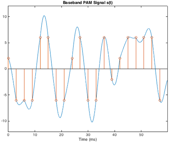
Figure 3. Example plot. showing a 4-PAM. Image used courtesy of Brian Evans [downloadable PowerPoint]
These PAM baseband signals could be upconverted, transmitted, and recovered by the receiver, and then the original digital data would be reconstructed based on the sequence of amplitudes.
However, predominant implementations of digital PAM use rectangular pulses, not truncated sinusoidal waveforms, and even the modulated and transmitted signal can look rather “digital.” Later in this article, we'll go over an example in the PAM Applications section; however, before getting into that, let's take a look at bits vs. symbols..
Understanding a PAM Waveform: Bit vs Symbol
A PAM waveform begins with ordinary digital data bits. Before these ones and zeros are mapped to amplitude multipliers, they must first be grouped into symbols. In this context, a symbol is a unit of transmitted information that contains one or more bits. In amplitude shift keying (ASK), each symbol represents binary one or binary zero because there are only two possible symbol states (on and off). You can see this play out in Figure 4.
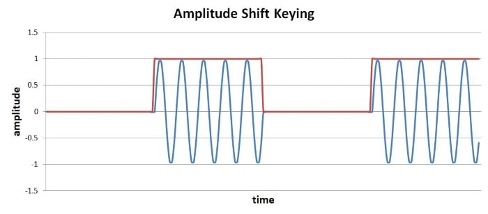
Figure 4. Example showing ASK.
Thus, ASK transfers one-bit symbols. It’s worth noting that ASK is a rudimentary version of PAM in which the pulse is a truncated sinusoid and the amplitude multipliers are zero (off) and one (on).
Keep in mind that PAM doesn’t have a fixed number of bits per symbol. Designers can choose how many amplitude levels are appropriate for a given PAM implementation, and the number of bits per symbol depends on the number of amplitude levels. If the system has two possible amplitudes (2-PAM), each symbol has two possible binary values, so the system transfers one bit per symbol. Four possible amplitudes (4-PAM) give two bits per symbol, eight amplitudes (8-PAM) give three bits per symbol, and so forth.
Pulse Amplitude Modulation Applications
A search through the technical literature connects PAM with optical links and high-speed computing interfaces, but perhaps the most notable application is Gigabit Ethernet. The 1000Base-T standard uses 5-PAM with rectangular pulses; the five amplitude levels are shown in the idealized waveform below in Figure 5.
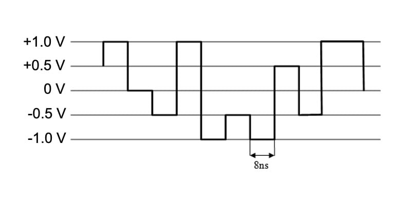
Figure 5. Example showing five amplitude levels in an idealized waveform. Image [adapted] used courtesy of Wiki Commons via Flominator
Note that a more realistic waveform would have rounded corners caused by the low-pass-filter effect of the transmission channel.
Gigabit Ethernet’s symbol frequency is 125 MHz, and the system transfers 8 bits per symbol by simultaneously employing 5-PAM on four separate differential pairs.
Though digital PAM, as described in this article, could be used for wireless communication, it is more closely associated with optical and wired transmission. For wireless data links, another form of amplitude modulation called quadrature amplitude modulation (QAM) is more common. You can learn more about QAM in AAC’s RF textbook.