Facebook
 Google
 GitHub
 Linkedin
Receiving and Sampling Signals in Digital Pulse Amplitude Modulation
The receiver in a digital PAM system must sample and measure the amplitude of a signal that is affected by the frequency response of the transmission channel.
In a previous article on digital pulse amplitude modulation (PAM), I explored the motivation for implementing digital PAM in a communication system, explained key PAM transmission concepts, and mentioned a few applications, one of which is Gigabit Ethernet. In this article, I’ll cover the basic requirements of a PAM receiver, which will lead us to a discussion of intersymbol interference (ISI) and the Nyquist ISI criterion.
Pulse Amplitude Demodulation
The procedure of extracting information from a baseband digital PAM waveform is conceptually straightforward. The receiver samples the signal every T seconds, where T is the period corresponding to the transmission frequency, and translates the measured amplitude into digital data according to the encoding scheme employed by the transmitter.
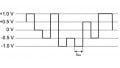
In the idealized plot below (Figure 1), the receiver decodes the transmitted signal by sampling in the center of the pulse interval (the green circles represent samples).
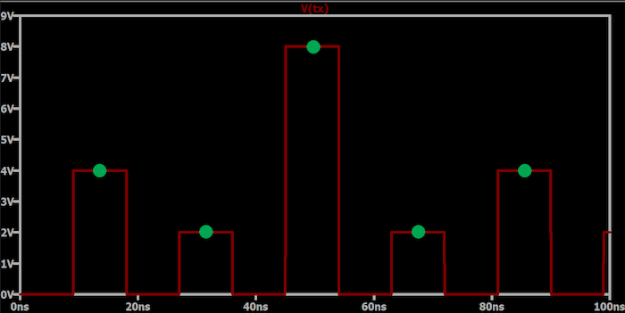
Figure 1. Example plot showing that the receiver decodes the signal transmission by sampling the pulse interval's center (green circles).
This plot suggests that the transmitted waveform, V(tx), is identical to the waveform sampled by the receiver. In a real-life system, the waveform would suffer degradation before arriving at the receiver. The nature and implications of this degradation are discussed below in the section “The Received Signal.”
Measuring Amplitude: Comparators and ADCs
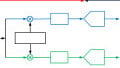
Since the digital PAM waveform contains multiple amplitudes rather than merely the “on” and “off” logic levels of a typical digital waveform, the receiver circuitry must include a means of deciding which of the predefined amplitude levels has just been sampled. This can be accomplished by clocked parallel comparators that compare the sampled signal to fixed reference voltages, followed by a decoder that translates the comparator outputs into a binary number. A comparator-based PAM demodulation block is illustrated in the example diagram in Figure 2.
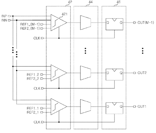
Figure 2. Block diagram showing a comparator-based PAM demodulation block. Image used courtesy of Chung et al
A more versatile solution uses analog-to-digital conversion followed by digital signal processing. Analog-to-digital converters (ADCs) and digital signal processors (DSPs) are so fast nowadays that this approach is feasible even for systems that require extremely high throughput. For example, an IEEE article published in 2019 presented a 4-PAM receiver architecture consisting of a successive approximation register (SAR) ADCs and a digital signal processor (supported by an equalizer and a variable-gain amplifier). The system achieved a low bit-error rate even when operating at 52 gigabits per second. That example IEEE article also specifies five other ADC-based 4-PAM receivers, all of which had maximum data rates greater than or equal to 28 gigabits per second.
The Received Signal: Circumventing Signal Degradation and Distortion
Let’s call the time-domain transmitted PAM signal x(t) and the received signal r(t). If the transmission channel were mathematically ideal and if we had no need for a higher-frequency carrier, we could say that x(t) = r(t). This equation means that the signal presented to the receiver’s input stage is identical to the signal produced by the transmitter’s output stage.
Though x(t) = r(t) sounds like wishful thinking, this assumption characterizes typical chip-to-chip digital signaling. When we send serial peripheral interface (SPI) signals from a microcontroller to a nearby application-specific IC (ASIC), for example, we don’t think much about the difference between x(t) and r(t). Since the transmission channel is just a short PCB trace and the signal frequencies are not particularly high, the effects of noise and limited channel bandwidth are usually negligible.
In an application such as Gigabit Ethernet, x(t) = r(t) is no longer a realistic assumption. First, we expect more noise since the transmission cable is longer and may pass through high-EMI (electromagnetic interference) environments. However, with good shielding and the noise-canceling properties inherent in differential signaling, the noise will remain a minor contribution to signal degradation.
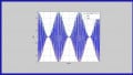
The more pressing concern is distortion caused by the transfer function of the channel: high signal frequencies combined with the limited bandwidth of the transmission line will convert a sequence of varying-amplitude pulses into rounded and potentially overlapping waveforms. The plot below (Figure 3) provides an extreme example of a pulse amplitude-modulated signal that has been distorted by a band-limited transmission channel.
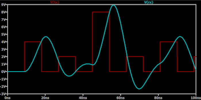
Figure 3. An example plot showing a PAM signal distorted by a band-limited transmission channel.
As you can see, the received pulses overlap to such an extent that the receiver will not reliably identify the transmitted pulse amplitude.
Intersymbol Interference
Since the overlap shown above is caused by one transmitted symbol interfering with another transmitted symbol, the effect is called intersymbol interference. The Fourier series for a square wave reminds us that rectangular pulses have infinite bandwidth, and since no realistic transmission channel offers infinite bandwidth, there will always be some degree of dispersion in the received waveform. The objective, then, is to design a PAM system such that dispersion does not create intersymbol interference and the consequent increase in bit error rate.
The Nyquist ISI Criterion
One thing to note is that intersymbol interference is not unique to digital PAM. It’s a common phenomenon that affects digital communication systems in general. ISI can be mitigated by incorporating an equalizer into the receiver; an equalizer attempts to compensate for the transfer function of the transmission channel. The ADC-based system mentioned above employs a sophisticated equalization scheme involving three equalizers: an analog equalizer that precedes the ADC and two discrete-time equalizers implemented in the DSP.
If you are determined to virtually eliminate ISI rather than mitigate it, you can design your system according to the Nyquist ISI criterion. This theorem requires that the received signal—meaning the original pulse after it has passed through the transmission channel and through a filter or equalizer that precedes the sampling circuitry—must have some nonzero value at time t = 0 and a value of zero at the sampling moments (i.e., at integer multiples of the sampling period).
In the previous article, we discussed a PAM system in which the baseband signal is generated using raised-cosine waveforms, and now we have an explanation for this choice: as depicted in Figure 4, the raised-cosine response satisfies the Nyquist ISI criterion.
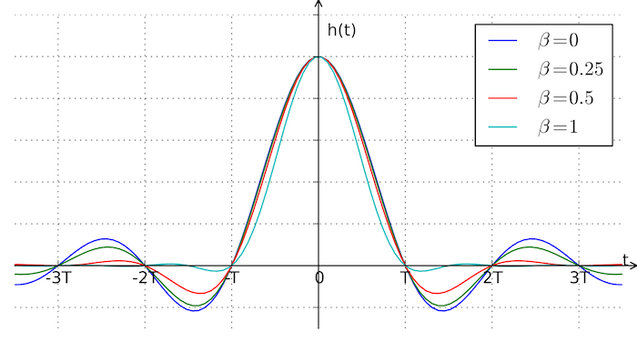
Figure 4. An example plot showing a raised-cosine response that satisfies the Nyquist ISI criterion. Image used courtesy of Wiki Commons and Krishnavedala via CC BY-SA 3.0
This plot shows the raised-cosine impulse response for different values of β, where β denotes the roll-off factor. Note that h(t) = 0 at the sampling moments (T, 2T, 3T, and so forth).
Overcoming Digital PAM Challenges
We discussed comparator- and ADC-based methods of converting pulse amplitude-modulated signals into binary data, and we looked at the difference between theoretical and practical PAM communication. Though not particularly complex at a conceptual level, digital PAM receivers require specialized techniques to overcome challenges associated with signal dispersion and intersymbol interference in high-performance systems.