 Facebook
 Google
 GitHub
 Linkedin
Characterizing the Moog Filter
This is Part 3 of a series of articles about the Moog ladder filter. In this article, we'll define the characteristics of the Moog filter, including its properties.
(article updated by author Feb 25, 2025)
Before moving on, please consider catching up with my previous Moog filter articles in this series:
Moog Filter Properties
Because this is a filter, we should understand what its (open-loop) characteristics are. We saw previously that the transfer function of the Moog filter is:
$$A = \pm \left ( \frac{1}{2j \omega r_e’ C + 1} \right )^n$$
Where re’ is the equivalent emitter resistance of the transistors, n is the number of filter stages, and A is positive for n even and negative for n odd. As long the number of stages is even, this is equivalent to an nth-order RC low-pass filter,
$$H(j\omega) = \left ( \frac{1}{j \omega R C + 1} \right )^n$$
And so we can use the same facts about RC filters to describe the Moog filter.
The cutoff frequency for a single stage of the filter is given by:
\[ f_c = \frac{1}{4 \pi r_e’ C} = \frac{I_{bias}}{8 \pi {V_T} C }\]
Where VT is the thermal voltage, given by
$$V_T = \frac{kT}{q} = 8.617 \times 10^{-5} T$$
Where T is temperature in kelvin. To control the cutoff frequency, then, we’ll need to change Ibias, but unfortunately the cutoff frequency only changes linearly. To get the 5 decades of cutoff frequency range necessary for audio, we’ll need to generate five decades of current values. Assuming the maximum drive current is a few milli-amps, we’ll have to get down to the tens of nano-amps.
Worse still, the current needs to be controlled by a potentiometer, whether linear or log tapered. Potentiometers can get expensive quickly, so there’s a premium placed on using standard audio taper or linear taper pots. Fortunately, we can drive the circuit with the simplest of exponential amplifiers: the BJT.
The actual circuit used in the Prodigy is shown in Figure 1. Recall that the current through a BJT is exponentially dependent on the base-emitter voltage,
$$I_C = I_S \exp \left ( \frac{V_{BE}}{V_T} \right )$$
So that if we drive VBE directly (instead of driving the base and having e.g. an emitter resistor), we can control IC as long as we don’t forward-bias the base-collector junction.
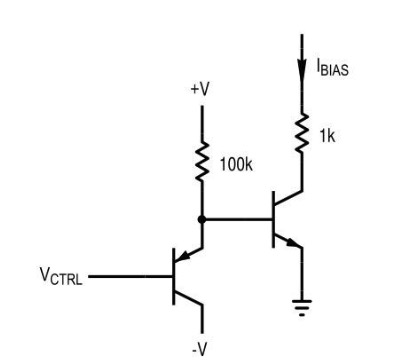
Figure 1. The exponential current source used in the Moog Prodigy synthesizer.
With the circuit in Figure 1, the base-emitter voltage is set directly by VCTRL, assuming a relatively constant VBE for the PNP transistor. The 100k resistor helps to ensure that the PNP transistor doesn’t saturate. Using the BJT diode equation, and the expression for the cutoff frequency, we can determine the cutoff frequency in terms of the control voltage VCTRL:
$$f_c = \frac{I_{bias}}{8 \pi V_T C} = \frac{I_S}{8 \pi V_T C}\exp(\frac{V_{ctrl} + 0.65}{V_T})$$
Unfortunately, this depends on the reverse-bias saturation current of the transistor, Is, which can vary significantly. For this reason, trimming is needed for VCTRL, and this is simply done in the Prodigy with trim pots.
The last filter characteristic of interest is the filter roll-off. The roll-off of the 4-stage Moog filter is, predictably, about 24dB/octave. This comes from the transfer function, which is the same as a 4-stage RC lowpass filter (with proper coupling). Each stage contributes an ideal attenuation of about 6dB/octave.
"Emphasis": Amplifier Feedback
The amount of feedback to the amplifier is called emphasis in electronic music, and we'll use this term here as well.
The first step in performing feedback analysis is to define the inputs and outputs of the circuit. Both the input and output can be viewed as voltages or currents, and this will help us define the type of feedback which will be in use. Depending on what we consider to be the input and output of the filter, our analysis can be quite simple or really challenging.
The Moog filter has a differential input. We can view the input terminals as currents (base currents) flowing into the transistors or as voltages either relative to ground, or as base-emitter voltages. The output voltage is taken from the final filter stage’s capacitor, with the left side being positive as shown and the right side being negative. The circuit we've constructed so far is shown in Figure 2.
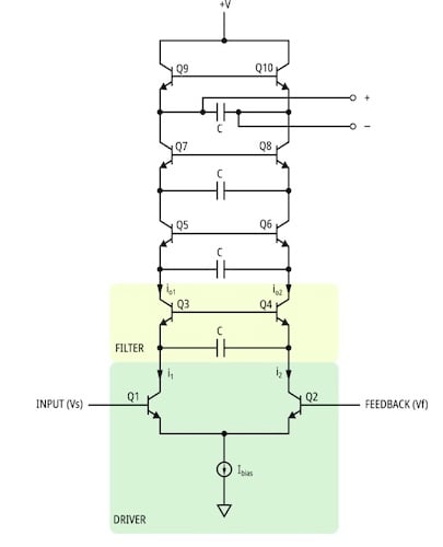
Figure 2. The Moog filter, with the driver section and one of the filter sections labeled.
The output of this filter, with four filter stages, is given by:
\[A=\left (\frac {1}{j2\omega r_e'C+1} \right )^4\]
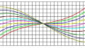
Where re’ = VT/Ibias. Note that this provides between 0 and 90 degrees of phase shift for each filter stage, meaning the output in the passband is roughly in-phase with the input, but through the cutoff frequency the phase shift will be around 180 degrees, and it approaches 360 degrees for higher frequencies. The positive and negative outputs are fed into a feedback network, and are applied back to the driver stage as feedback (Vf). The feedback network is shown in Figure 3.

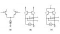
Figure 3. The feedback network, with component values as in the Moog Prodigy.
This feedback network, reproduced with component values from the Moog Prodigy synthesizer, consists of two Darlington transistor arrangements feeding an inverting op-amp, passing through a passive output network giving the feedback voltage Vf. The op-amp is an LM4558 general purpose op-amp. The transistors act as buffers and the op-amp is arranged as a difference amplifier with gain set to -6.81 with the signal polarity as shown. The output network provides a phase-inversion, and attenuation. A “bleed” resistor and potentiometer is given to balance the voltage-controlled filter bias point, and we can largely ignore this part.
Now let’s turn our attention to the phase shift network. The emphasis knob goes from left (no emphasis) clockwise to the right (full emphasis). The emphasis resistors, the 10uF capacitor, and the 1k output resistor compose a high-pass filter which provides attenuation. This would be a well-attenuated high-pass filter, but because the capacitor value is so high, it has little effect above 10Hz. Thus, we’re left with a simple voltage divider, providing a gain of 0.02 (no emphasis) to 1 (full emphasis and trim).
The overall feedback transfer characteristic, B, is:
\[B =\frac{-6.81k}{R_{emph}+1k}\]
Where Remph is the total emphasis resistance (emphasis and emphasis trim).
From here, to really get into the stability of the feedback loop, we should turn our attention to the Laplace domain. A previous version of this article used the expression for loop gain, AB, but as one reader (none other than Bernie Hutchinson!) pointed out, the analysis was flawed.
Bernie’s original analysis was published as Additional Design Ideas for Voltage-Controlled Filters (1978). This was amended by Richard Bjorkman a year later, in an article titled A Brief Note on Polygon Filters (1979). Other noteworthy works include the analysis taken up by Stilson and Smith, Analyzing the Moog VCF with Considerations for Digital Implementation (1996) and the quite thorough paper by Tim Stinchcombe, Analysis of the Moog Transistor Ladder and Derivative Filters (2008). The interested reader can refer to these sources for more complete feedback analysis.
Now, anyone who has used a Moog filter in a synthesizer can attest to the fact that this instability is actually a characteristic feature of the filter. The cutoff-frequency oscillations caused by the instability when the emphasis is turned up very high produce a peculiar sine-wave which can be controlled by the cutoff frequency knob on the synthesizer. This sound is just another interesting part of the Moog’s analog sound and behavior.

Figure 5. The full Moog ladder filter with feedback and component values the same as in the Moog Prodigy.
Conclusion
So far in this series, we’ve investigated the behavior of the Moog ladder filter, roughly as it appeared in the Moog Prodigy synthesizer. We made a lot of assumptions, and waved our hands about freely, so there’s a lot still to be said for this topology. In future articles, we will explore the practical aspects of making a Moog ladder filter, and we will look at some copy-cat filters designed to get around the Moog patent.
Related Content


Hi Sam – hope your analysis of the Moog 4-pole is progressing.
At the half-power frequency of the first-order low-pass,
[ 1 /(2 pi RC)], the loss is 1/sqrt(2) and the phase shift is 45 degrees. Four cascaded stages thus have a loss to ¼ and a total phase shift of 180 degrees (an inversion). Fed back to an inverting input with a gain of 4 (your B, my g), this is a POSITIVE feedback of +1 and thus represents an oscillator at [ 1 /(2 pi RC)]. With B less than 4, we have the classic Q-enhancement (highly resonant as B approaches 4), but a STABLE FILTER. S-plane (Laplace) analysis tells everything (stability, frequency-response, time-response), well beyond feedback analysis. (Please see my comments on your Part 1.)
In practice, oscillation likely requires a value of B that is just ever so slightly in excess of 4, just to get started. With B intentionally greater than 4, we have an oscillator clipping in the first stage (slight variation of frequency and of course with significant harmonic distortion in this first stage, but with the subsequent filtering of the harmonics down the line). It is likely that this clipping is responsible for the “mystic” “Moog Sound” that is so valuable musically and slightly embarrassing (non-linear!) technically.
In your analysis which is faulty in several places: (1) you inverted Ohm’s Law (re’ = Ibias/VT) and (2) messed up the equations for fc. You have also tried to calculated the “loop-gain” (Bode – first order) in terms of omega and C but not specified omega, notwithstanding the fact that an s-plane approach is necessary for the full stability picture.
It is of course quite possible that the circuit you give works in practice, despite an incorrect analysis/description. As I stated the filter is stable and shows resonance as B (my g) increases from 0 to +4. The circuit you give shows a gain 6.81 coming out of the differential amplifier so needs an attenuation of 0.587 just to get down to 4, but still reach 4 or a small bit above 4. The attenuator is the voltage divider: your B = 6.81k/(Remph + 1k) where Remph is the total emphasis resistance (emphasis and emphasis trim). That is, Remph should get as low as about 703 ohms, or (intentionally) a bit lower.
You have chosen the fix the trimmer at 1k. And the 50k pot is at about 92% (your Fig. 4) for feedback giving loop gain of +1. If this is a linear pot (?), the remaining 8% of the 50k pot would be 4k, added to the 1k trimmer; there would be no significant enhancement, ever. What am I missing?
Is it NOT the actual case that the 1k trimmer serves to limit the input leg of the voltage divider to about 700 ohms so that when the 50k is fully CW to 0 ohms the feedback is just a bit above 4?
Best wishes - Bernie