 Facebook
 Google
 GitHub
 Linkedin
How to Multiply RF Signals without a Multiplier: The Switching Mixer
This article introduces an important technique used to perform frequency mixing in modern RF circuits.
This article introduces an important technique used to perform frequency mixing in modern RF circuits.
The mixer is a fundamental component in RF circuit design. An RF mixer (in contrast to an audio mixer) performs mathematical multiplication, the effect of which is frequency translation. A “downconversion” mixer refers to a mixer that is incorporated into an RF receiver and used to shift received signals down to baseband or intermediate frequencies.
This is all perfectly straightforward as long as we stay in the mathematical realm. Look at the trig identities and you’ll see exactly what happens when you multiply two sinusoids. However, electronics are generally implemented via circuitry rather than formulas, and this means that we need a multiplier circuit. More specifically, we need a circuit that performs multiplication at high (perhaps extremely high) frequencies.
The Analog Mixer
It is possible to design a circuit that accepts two analog inputs and produces an output signal corresponding to the product of the inputs. These are built around diodes or transistors and take advantage of the multiplicative relationships that are inherent characteristics of these devices. I refer to these devices as “analog” mixers to emphasize the fact that the multiplication does not involve a digital switching operation.
This analog approach to mixing is pleasantly intuitive. Unfortunately, modern RF receivers frequently adopt the far-less-intuitive digital/switching approach as a means of reducing power consumption. Analog mixers are by no means useless, and the diode-based versions are valuable in very-high-frequency systems where performance would be impaired by the inevitable bandwidth limitations exhibited by BJTs and FETs. Nonetheless, “digital” downconversion mixers—or “switching” mixers, or (in certain implementations) “current-commutating” mixers—are widely used in today’s RF systems, and consequently it’s a good idea to understand what they are and how they work.
The Switching Mixer
The first conceptual hurdle presented by the switching mixer is the local oscillator (LO) signal. It’s a square wave (or, if it’s a sine wave, the mixer treats it as though it’s a square wave). As far as I’m concerned this is unforgivable. In my vision of the world, RF is the apogee of analog electronics—sinusoids everywhere you look, good-old-fashioned mathematical relationships... even digital data is transferred using analog waveforms. Once you accept the fact that this switching mixer business allows a clunky digital signal into the smoothly varying world of RF, you then have to confront the fact that on/off switching is a form of multiplication.
The following diagram represents the most basic manifestation of a downconversion switching mixer.
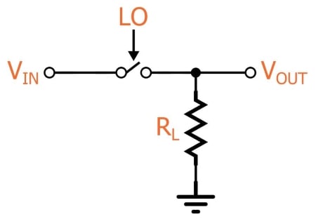
This is, indeed, nothing more than a voltage-controlled switch. The received RF signal is applied as the input voltage, and the LO controls the switch. So all we’re really doing here is turning the input signal on and off according to the frequency of the LO.
The first question that I know you are asking: “How can this possibly be mixing?” Well, first remember that mixing is multiplication. If you think of the LO as a square wave that transitions between 0 V and 1 V, the switch is effectively multiplying the input signal by the LO: When the switch is closed, the output is equal to the input multiplied by one. When the switch is open, the output is equal to the input multiplied by zero.
Next question: “How can this possibly be equivalent to multiplying by a sinusoid? Sure, the frequencies might be the same, but the mathematical relationships indicating that multiplication produces frequency translation are based on two sinusoids, not one sinusoid and one square wave.” Excellent point, but you’re forgetting one thing: the sine wave is inside that square wave. Fourier has told us and we dare not doubt him. We can’t see it because it is hopelessly blended with all the harmonic components, but it’s in there somewhere, and that means the following: if this switch arrangement is multiplying the input signal by the LO square wave, it is also multiplying the input signal by a sinusoid with frequency equal to the LO frequency.
At this point you’re probably wondering why we would want to foul up the multiplication with all these harmonic components, but harmonic energy can be suppressed via filtering, and it turns out that in many cases the harmonics are less problematic than the disadvantages presented by an analog-mixer-based solution.
Does This Really Work?
Let’s look at an example. Here’s the LTspice circuit:
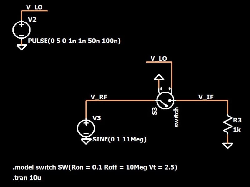
Let’s imagine that this mixer is shifting the received RF signal down to the intermediate frequency (IF). The received signal is at 11 MHz, and the LO is a 10 MHz square wave. The multiplication is implemented by means of a voltage-controlled switch connected to the LO signal. The frequency of the output signal should be equal to the input frequency minus the LO frequency, i.e., 1 MHz.
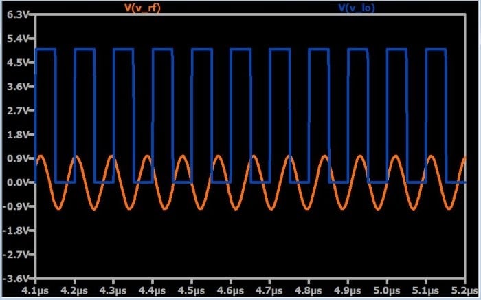
Let’s take a look at some waveforms. This first plot shows the input signal and the LO.
Here is the same plot but with the output included in a separate pane.
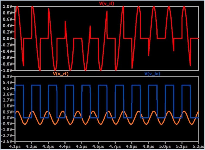
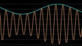
You can see the multiplication relationship here, but so far it looks like all we’ve done is hack up a perfectly good sine wave. The picture starts to emerge when you zoom out, though:
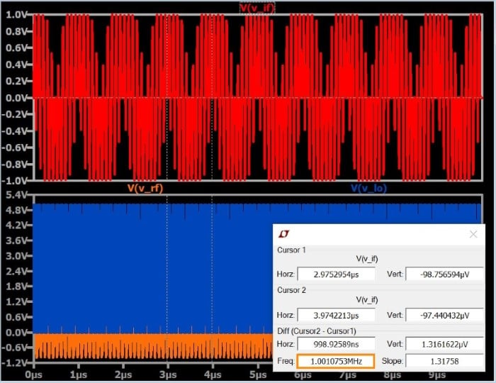
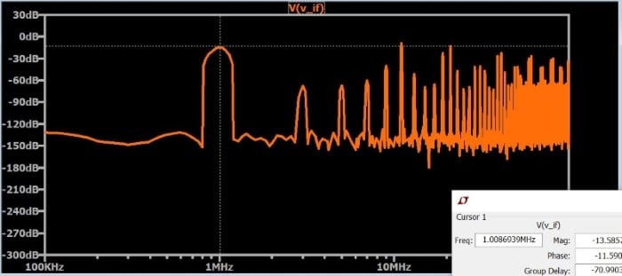
You can see that all this hacking has somehow resulted in something that looks vaguely sinusoidal, and this vaguely sinusoidal thing happens to have a frequency of 1 MHz. Our final confirmation comes from the FFT, which shows a dominant spike at 1 MHz (along with lots of harmonic content):
Conclusion
Mixer circuitry is an extensive topic, and this article is nothing more than an introduction to the basic concepts of switch-based mixing. Nonetheless, we have to start somewhere, and you actually can create a real mixer by implementing the above circuit using a CMOS transmission gate in place of the idealized voltage-controlled switch.
If there’s interest, we could explore this topic further in future articles. If you’d like to see more information on switching mixers, please leave a comment and let me know.


While this is an introduction article, it is a great one! Please have more articles on the topic. 😊
I agree! This is a very interesting topic and it flowed well. More on RF, mixing and, perhaps, antennas…
Thank you Mr. Keim. You are doing exceptional work!
A VERY nice explanation of a digital mixer. In addition to the dominant FFT frequency of 1 MHz, I also noted spikes at the maximum amplitude at 10 MHz and 11 MHz (the 2 fundamental frequencies). I assume there also a dominant FFT spike at 21 MHz, representing the sum of the fundamental frequencies also?