 Facebook
 Google
 GitHub
 Linkedin
Need a Current Regulator? Use a Voltage Regulator!
This article, part of AAC’s Analog Circuit Collection, shows you how linear voltage regulators can also be handy in constant-current applications.
This article, part of AAC’s Analog Circuit Collection, shows you how linear voltage regulators can also be handy in constant-current applications.
Linear voltage regulators, also (somewhat inaccurately) called LDOs, are one of the most common electronic components. The LM7805, for example, has acquired an almost legendary status and would certainly be included in the integrated-circuit hall of fame, if such a thing existed. This app note from Texas Instruments says it well: linear regulator ICs are “so easy to use” that they’re practically “foolproof” and “so inexpensive” that they are generally among the cheapest components in a design.
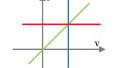
Indeed, linear regulators are user-friendly, effective, and versatile. And, in fact, they may be even more versatile than you think. Linear-regulator topologies are built around negative feedback, as shown in the following diagram taken from the same app note:

Diagram taken from this TI app note.
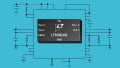
Negative feedback is a very useful thing, especially when it’s combined with a fixed current source, as is the case with the LT3085 voltage regulator from Linear Tech. The following diagram conveys the internal functionality of this device.

Diagram taken from the LT3085 datasheet.
In previous articles (a project on designing a color sensor and an exploration of the voltage-to-current converter), we explored the use of negative feedback in voltage-to-current converters that can precisely control the brightness of an LED. If you’re familiar with these techniques, it should not be too surprising to learn that we can actually use a voltage regulator like the LT3085 to generate a constant current.
In this article, we’ll look at a simple LT3085-based LED driver.
Linear Regulator vs. Op-Amp
Before we analyze the circuit, itself, we should discuss the advantages of the linear-regulator approach to constant-current generation. The op-amp methods presented in previous articles are undoubtedly effective, so why bother with a new technique?
Here are some points to consider:
- Most op-amps are not designed for high output current, so a linear-regulator-based circuit allows you to avoid the output-current limitations of typical op-amps.
- Regulator ICs incorporate overtemperature protection.
- Linear regulators offer greater tolerance of large input voltages and high power dissipation.
- You might be able to find a single part that is adequate for almost all of your voltage-regulation and current-generation requirements. My least favorite aspect of schematic/PCB design is creating new library components, so I try to use parts that are likely to come in handy for future designs.
The LT3085 as Voltage Regulator
Let’s briefly examine the voltage-regulation functionality of the LT3085. This information will help us to understand the current-source implementation.
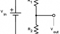
Here’s a typical voltage-regulator configuration:

Diagram taken from the LT3085 datasheet.
The current source (10 µA) creates a voltage across RSET. This voltage appears at the amplifier’s non-inverting input terminal. The negative-feedback action ensures that the voltage at the inverting terminal is equal to the voltage at the non-inverting terminal; in other words, the output voltage equals the voltage across RSET. The output capacitor is needed to ensure stability, and the transistor connected to the amplifier’s output terminal will look very familiar if you’ve read my article on How to Buffer an Op-Amp Output for Higher Current.
From Voltage to Current
The purpose of a voltage regulator is to provide a constant output voltage regardless of the load resistance. In other words, an ideal regulator would produce a voltage that is (for example) exactly 3.3 V when connected to a 100 kΩ load and exactly 3.3 V when connected to a 5 Ω load. What changes, of course, is the load current, which is determined completely by the load resistance (because the voltage across the load doesn’t change).
What happens, then, if we give the ideal voltage regulator a fixed load resistance? If load voltage doesn’t change and load resistance doesn’t change, and if Ohm’s law is still in effect, then the current won’t change either.
Voilà: a current source.
The following diagram shows you how to co-opt the LT3085 for your LED-driving objectives.

Diagram taken from the LT3085 datasheet.
Here’s how it works:
- The internal current source sends 10 µA through R1, generating a voltage that will be equal to the output voltage (i.e., the voltage across R2).
- This output voltage is constant (because R1’s resistance and the value of the internal current source are constant).
- This constant output voltage will produce a constant current through R2, because R2’s resistance is constant.
- The amplifier’s inverting input terminal doesn’t supply current, so almost all the R2 current comes from the positive supply through the transistor connected to the amplifier’s output terminal. (I say “almost” because the BJT’s emitter current is the sum of the base current and the collector current, but the base current is much smaller than the collector current.)
- The LED is in series with the BJT’s collector, and thus the current through the LED is fixed and (almost) equal to the current flowing through R2.
The current through the LED can be modified by changing the value of R1 or of R2; as shown in the following equation, the LED current is simply the value of the internal current source multiplied by the ratio of R1 to R2.
$$I_{LED}=\frac{((10\mu A)\times R1)}{R2}=10\mu A\ \times \frac{R1}{R2}$$
I would call this a pretty handy circuit: The design process is extremely simple, and just a handful of components are needed. If you replace one of the resistors with a potentiometer, the result is a high-precision, wide-input-voltage-range, overtemperature-protected, variable-current LED driver that can supply up to 500 mA.
And of course it’s not limited to LEDs; you could just as easily use it with, say, a resistive heating element. This would allow you to generate constant heat (because P = I2R) despite variations in supply voltage.
Conclusion
We’ve discussed a simple yet high-performance current source that is based on a voltage regulator IC from Linear Tech. I assume that similar regulator topologies are available from other manufacturers.
I like to always include SPICE simulations in Analog Circuit Collection articles, but in this case it seemed truly unnecessary. However, before I wrote the article I confirmed that LTspice does include an LT3085 component (in the “[PowerProducts]” folder). So although I didn’t provide a simulation, I did make sure to use a part that could easily be simulated, if you want to explore this circuit further.
Related Content


The term “LDO” is NOT an incorrect term, but rather the descriptor for a Low Drop Out linear regulator. Standard linear regulators require several volts of headroom in the supply voltage, while an LDO regulator requires less excess voltage. An example is the 7805, which requires a supply voltage of at least 8 volts, and totally loses control when the supply drops to 6 or 7 volts. Certainly not all linear regulators are low dropout devices, and so some don’t earn that name. But it is not always incorrect.
Hey Robert, thank you for this useful circuit. I simulated it with LTspice and it works as advertised.