Facebook
 Google
 GitHub
 Linkedin
Restoring Digital Signals in Pass-Transistor Logic
This article takes a detailed look at the way in which pass-transistor logic degrades a signal and how this signal degradation can be remedied.
This article takes a detailed look at the way in which pass-transistor logic degrades a signal and how this signal degradation can be remedied.
Supporting Information
- The CMOS Transmission Gate
- Introduction to Pass-Transistor Logic
- Digital Design with Pass-Transistor Logic
- Implementing Multiplexers with Pass-Transistor Logic
- Implementing Sequential Circuitry with Pass-Transistor Logic
If you’ve read the previous articles, you are well acquainted with the fact that implementing pass-transistor logic with an NMOS switch results in problematic signal degradation. We can greatly improve signal integrity by using a CMOS transmission gate instead of an NMOS switch. However, it’s hard to get motivated to fill up a circuit with transmission gates because by doing this we often lose the only major benefit that PTL offers, namely, significant reduction in transistor count. A CMOS transmission gate requires not only an additional transistor in the switch itself but also an inverter for the complemented control signal.
The NMOS Switch
Unfortunately, an NMOS transistor is simply not a good device for logic-level switching applications. The problem here is that the existence of a current path depends upon the presence of a gate voltage that is higher than the source voltage.
This issue is easily overcome if the circuit has access to a control voltage that is higher than the voltage levels that will be passed through the switch. But in the context of a standard digital circuit, we can never expect to have more than two voltages: the logic-high voltage and the logic-low voltage. Thus, if a 3.3 V signal is applied to the gate, the FET simply cannot effectively pass a 3.3 V signal from input to output.
An NMOS switch passes a “strong” zero and a “weak” one: When a logic-high voltage is applied to the gate (to turn the switch on) and a logic-low signal is applied to the input terminal, the gate voltage is significantly higher than the voltage at the other two terminals. This results in a low-resistance channel between input and output. The situation is very different, though, when we apply a logic-high signal to the input terminal. We no longer have a large voltage difference between the gate and the other two terminals, and electrical performance deteriorates as channel resistance increases.
We can use the following LTspice circuit to experiment with the behavior of an NMOS switch.

A 3.3 V control signal is applied to the gate, and the input signal transitions between ground and 3.3 V. The small amount of load capacitance represents the input capacitance of the downstream circuitry.

You can see that the slope of the output signal greatly diminishes when the difference between the gate voltage and the output voltage drops below a certain level. The output voltage begins to rise very slowly, and it doesn’t reach the logic-high voltage before the beginning of the next cycle. There is also a significant delay in the negative transition, though the output voltage does eventually reach ground. This plot gives you a clear idea of what we mean by “strong” zero and “weak” one.
Can We Use an Inverter?
You might be thinking that there’s a very simple solution to this issue of signal degradation: What if we apply the PTL signal to the gate of a standard inverter? At first glance, it seems that this would restore the logic levels, clean up the edges, and provide low-resistance paths to the supply rail and ground. What could be better?
My guess is that you could get away with this in many situations, but in general it is not the recommended solution. The problem is that the logic-high voltage coming out of the NMOS switch might be low enough to create a conductive channel in the inverter’s PMOS device.
Usually, when the input to an inverter is logic high, the NMOS transistor is fully conducting and the PMOS transistor is fully cut off. But as the input voltage drops below the supply voltage, the source-to-gate voltage of the PMOS increases, perhaps to the point at which non-trivial amounts of current will flow from source to drain.
This is a problem, because with the NMOS fully conducting, we now have a current path from the supply rail to ground. The final result here is wasted power: the inverter dissipates power not only during switching but also whenever the input is logic high.
A basic inverter, then, is not an adequate method of PTL signal restoration. It’s almost an adequate method, though—all we need to do is add one strategically connected PMOS transistor.
The PTL Signal Restorer
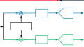
The following LTspice schematic shows a clever circuit that can be used to greatly improve the characteristics of the output signal delivered by an NMOS switch.

The operation of the circuit is fairly straightforward. When the input is logic low, the NMOS passes a strong logic low to the inverter. Under these conditions, M2 does not affect the circuit, because its gate voltage is the strong logic high generated by the inverter.
When the input is logic high, the NMOS initially delivers a weak logic high to the inverter. This weak logic high is not problematic, though, because it rapidly becomes a strong logic high: as soon as the output of the inverter transitions to logic low, M2 turns on, establishing a low-resistance path between the PTL output node and the supply rail.
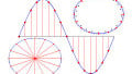
The following plot demonstrates the efficacy of this circuit.

As you can see, logic levels have been restored and delays have been eliminated. And as a bonus, the signal-restoration circuit also produces a high-quality inverted version of the output signal:

This inverted signal might come in handy if the downstream circuitry uses a CMOS transmission gate.
Conclusion
I hope that you have enjoyed this series on pass-transistor logic. It’s an interesting alternative to standard inverter-based digital design, and this article gives you a means of mitigating the effects of PTL’s inferior electrical performance. If you have any arguments against or in favor of pass-transistor-based implementations of digital functionality, feel free to share your thoughts in a comment.