Facebook
 Google
 GitHub
 Linkedin
The Effect of Offset Voltage on a Precision Current Source
In this article, we’ll continue our discussion of an LTspice circuit that helps us to predict how offset-voltage variations will influence circuit performance.
In the previous article, we discussed how an LTspice circuit can help us analyze the effect of unpredictable offset voltage on a precision current-source circuit. In this article, we’ll continue this discussion by exploring an LTspice circuit that can help us to predict how offset-voltage variations will influence circuit performance.
Analyzing Offset Voltage Distribution
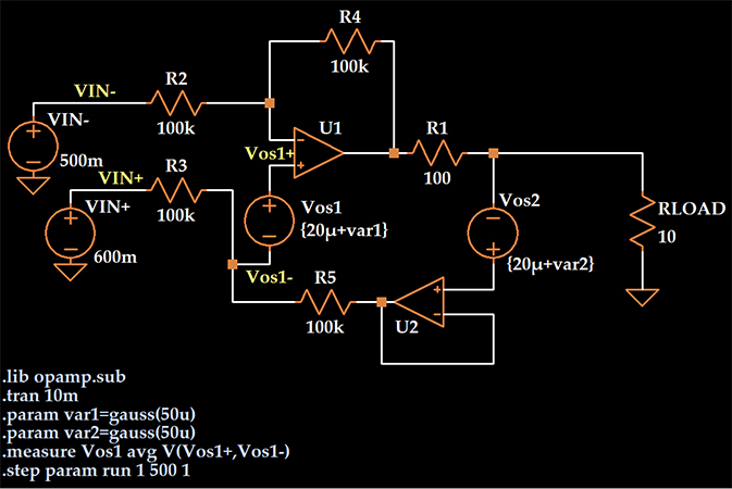
Here’s the LTspice schematic that I presented at the end of the previous article:
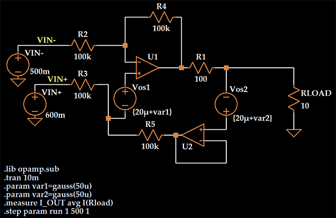
I incorporated offset voltage into the circuit by adding a voltage source in series with the non-inverting input terminal of each op-amp.
I wanted to create a distribution of offset voltages that is similar to the distribution reported for the AD8606 precision op-amp, and to accomplish this I specified a typical value of 20 μV for Vos1 and Vos2 and added a Gaussian variable to this typical value.
The argument passed to the gauss function is the standard deviation, so I’ve created two DC voltage sources with values that vary randomly according to a normal distribution with a mean of 20 μV and a standard deviation of 50 μV.
We need to confirm that the distribution produced by LTspice is consistent with the AD8606’s measured distribution of offset voltages. To do this, I will simulate the circuit, plot the Vos1 values, save them to a file, import them into Excel, and inspect the histogram.
Note in the schematic below that I have changed the “.measure” statement so that it records the value of Vos1 rather than the load current.
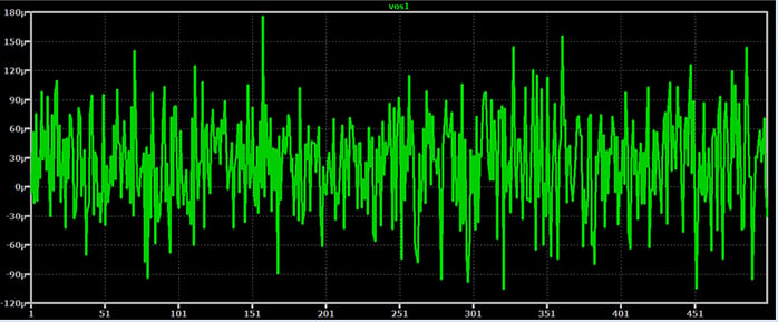
If I open the SPICE Error Log, right-click, and select “Plot .step’d .meas data,” I obtain the following plot:
Producing the Histogram
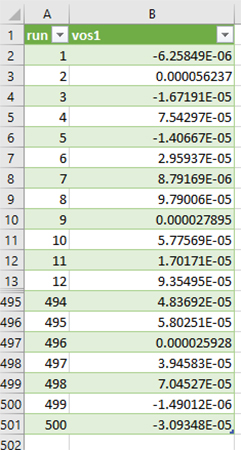
I can now save this data by right-clicking and selecting “File” -> “Export data as text.” I import this data into Excel, and I have 500 different values of offset voltage:
First, let’s check the mean and standard deviation to ensure that they are similar to what they should be, i.e., 20 μV and 50 μV.
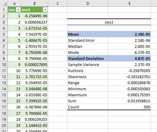
That’s pretty good; the mean is 23.9 μV and the standard deviation is 48.7 μV. The actual values would be closer to the expected values if the simulation included a larger number of runs. For example, with 4000 runs, the mean was 20.8 μV and the standard deviation was 50.6 μV.
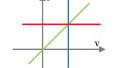
Now let’s take a look at the histogram:
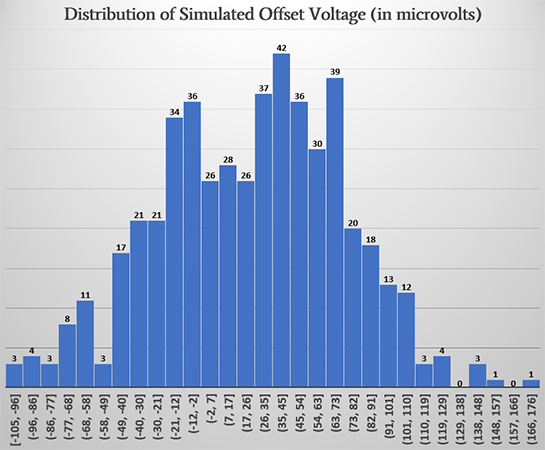
With a sample size of 500, we definitely don’t get a perfect normal distribution, but when I compare the basic characteristics to those of the AD8606 distribution (shown below), I’m satisfied.
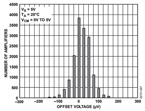
Plot taken from the AD8606 datasheet. Image used courtesy of Analog Devices
Simulation Results
Before performing the simulation, I restored the “.measure” statement to its original state, i.e., “.measure I_OUT avg I(Rload).” The expected load current is 1 mA. I first ran the simulation with the Vos1 and Vos2 sources set to zero; here are the simulated load current values for 500 runs:
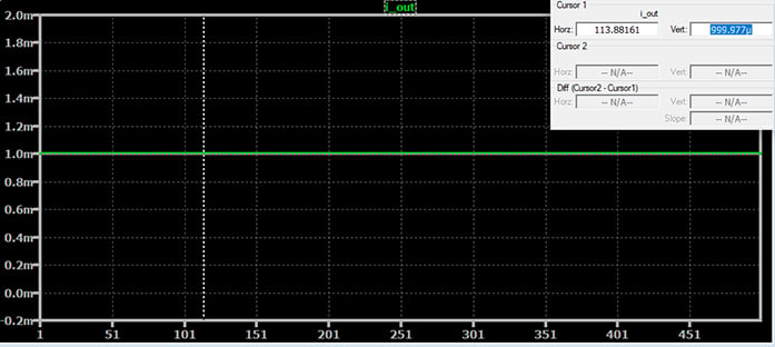
The load current is the same for every run, which is not at all surprising since no parameters were changing and consequently every run had the exact same circuit. We also observe that some sort of non-ideal behavior is built into the op-amp component because the simulated load current is 999.977 μA instead of 1 mA. So we’re starting off with an error of 23 nA in the negative direction.
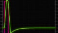
Here are the results when offset-voltage behavior is included:
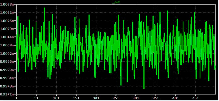
We can see from an initial inspection that the effect has not been catastrophic. The average output current has shifted slightly, and we have maximum deviation from the mean on the order of 3 μA.
Analysis in Excel indicates that the average output current is 1.00068 mA. The worst-case error (with respect to the theoretical value of 1 mA) is 3.5 μA in the positive direction and 2.4 μA in the negative direction.
These are definitely small errors, but they make a nontrivial contribution to the overall error in the circuit, especially when we compare them to the effect of resistor tolerance and temperature:
In a previous article, we generated maximum deviation of about +5 μA/–10 μA by subjecting all the resistors to 0.1% tolerance and varying the operating temperature from –40°C to +125°C. Offset voltage alone created maximum deviation of +3.5 μA/–2.4 μA.
We also have to keep in mind that the offset-voltage performance of the AD8606 is quite good. There are many op-amps currently in production that have more offset voltage than the AD8606.
Conclusion
We’ve used DC voltage sources and LTspice’s gauss function to simulate the effect of an op-amp’s input offset voltage on the precision of a voltage-controlled current source. We saw that offset voltage makes a small but non-negligible contribution to the overall output error, even when the circuit is built around op-amps that are intended for high-precision applications.