 Facebook
 Google
 GitHub
 Linkedin
Understanding Operational Amplifier Slew Rate
This article explores an important limitation that can cause a real-life op-amp to deviate from the behavior of its idealized counterpart.
What is slew rate in operational amplifiers? In this article, we'll define slew rate, talk about its causes, and contrast it to the concept of bandwidth.
First, though, let's consider the differences between ideal and real op amps so we can understand how slew rate can cause differences between the two.
The Ideal (Learning with Idealized Op Amps)
When we first learn about operational amplifiers, we typically study a reasonably accurate ideal model that simplifies analysis and helps us to develop intuitive awareness of op-amp functionality. The following diagram conveys characteristics of this idealized op-amp.
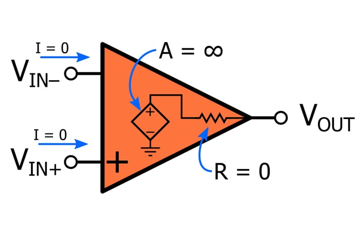
When we analyze a circuit using the ideal model, we make the following assumptions:
- No current flows into or out of the op-amp’s input terminals.
- The open-loop gain of the op-amp is infinite (this leads to the virtual short simplification) and has no frequency dependence.
- The output impedance is zero.
The Real (Designing with Real Op Amps)
Eventually, we have to come to terms with op-amp nonidealities, which affect both static operation and dynamic operation. Current does flow through the input terminals, open-loop gain isn’t infinite, output impedance isn’t zero, and the frequency of the input signal affects the characteristics of the output signal.
In this article, we’re going to focus on an op-amp limitation that influences dynamic response and that is perhaps somewhat easy to forget, because in most cases its effect on circuit operation is less noticeable and less significant than the effect of the op-amp’s open-loop frequency response. This nonideality is called slew rate.
What Is Slew Rate?
Slew rate is the maximum rate of voltage change that can be generated by the op-amp’s output circuitry. It is measured as voltage relative to time, and the typical unit used in datasheets is volts per microsecond (V/µs).
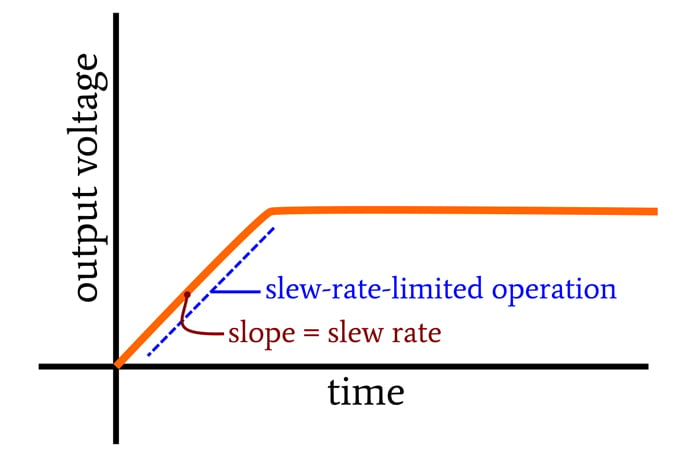
Let’s say you have an op-amp and apply an input signal that would, in an ideal environment, generate an output signal with a slope of 10 V/µs. If the slew rate of the op-amp is 2 V/µs, the output signal will reflect the slewing behavior of the op-amp rather than the expected output signal. When the op-amp is in this “slew-rate-limited” state, the output is a linear ramp with a slope equal to the slew rate:
What Causes Slew Rate?
A full explanation of slew rate at the transistor level is beyond the scope of this article (and of my expertise), but in general, the phenomenon emerges from two characteristics of op-amp dynamic response.
First, common engineering sense tells us that the op-amp’s output cannot respond instantaneously to a change in input. Thus, we have an inevitable delay from input change to output change.
Second, when an op-amp is connected in a negative-feedback configuration, this delay will, in some cases, lead to a large difference between the voltage applied to the inverting input terminal and the voltage applied to the non-inverting input terminal. This large differential voltage modifies the behavior of the differential-pair input stage in such a way that the output voltage increases (or decreases) linearly, i.e., VOUT(t) = SR×t. The slew rate (SR) is strongly influenced by the amount of compensation capacitance.
Slew Rate vs. Bandwidth
At first glance, it may seem that slew rate is simply the time-domain manifestation of the op-amp’s bandwidth limitations. One might assume that when we’re working with sinusoidal signals, the op-amp loses gain at high frequencies, and when we’re working with transient events, the same basic mechanism limits the maximum rate of change in the output signal. However, it’s important to recognize that frequency response and slew rate are distinct phenomena and that the effects of these two phenomena differ in a fundamental way.
Poles in the op-amp’s transfer function lead to typical low-pass-filter behavior; signal amplitude decreases as frequency increases, and phase shift occurs. But these effects are linear, and consequently they do not introduce distortion into the output signal.
Slewing, on the other hand, is a nonlinear effect. If a sinusoidal input signal multiplied by the gain of the op-amp results in a slope that is higher than the op-amp’s slew rate, a portion of the output waveform will be a straight line rather than a curving section of a sinusoid. Thus, slewing can modify the shape of a signal and is, therefore, a source of distortion rather than mere modifications of amplitude or phase.
Practical Slew Rate Considerations
The vast selection of op-amps currently available to engineers covers a very wide range of slew rates. Some devices offer a few volts per microsecond or even less, and others offer hundreds of volts per microsecond. If you’re designing a circuit that involves transient signals, high-amplitude sinusoids, or digital waveforms, give a quick thought to slew rate before you choose your op-amp.
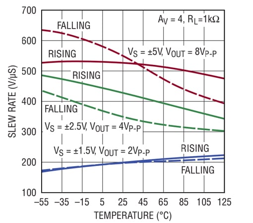
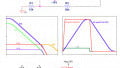
This plot—taken from the datasheet for the LTC6228, a high-slew-rate amplifier from Linear Tech/Analog Devices—demonstrates that various parameters influence slew-rate performance.
As shown in the table below, there is a strong relationship between current consumption and slew rate. You’ll have to do some careful component selection if you’re trying to incorporate good slewing performance into a very-low-power design.
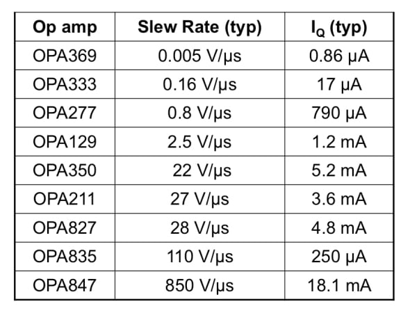
This table is from a presentation on slew rate produced by Texas Instruments. I definitely recommend that you read through the presentation if you’re looking for more information on this topic.
Conclusion
I hope that this article has provided a foundational understanding of slew rate and its role in op-amp implementation. If you'd like to learn more, consider reading Dr. Sergio Franco's article on how to increase the slew rate of a composite operational amplifier.
If you’ve ever worked on a system in which slew rate was a major design challenge or noticeably impaired the overall functionality of a circuit, feel free to share your experiences in the comments section.
Related Content


See also: https://www.researchgate.net/profile/Hugo_Coolens/publication/239522485_Closer_look_at_the_slew_rate_criterion/links/00b7d51c0ac2704e92000000/Closer-look-at-the-slew-rate-criterion.pdf