Facebook
 Google
 GitHub
 Linkedin
Zero-Crossing Detectors
Suppose you need to start a timer or counter at the exact moment when the line voltage crosses the zero line. How do you determine this point without bringing the line voltage into the IC?
A simple external resistor connected to the line voltage will do the trick, as illustrated in Figure 18-25. In this bipolar design, you can use the (usually unpleasant) fact that the transistor differential pair in the first stage can cut off the transistor that follows in the second stage.
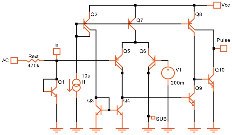
Figure 18-25. Bipolar zero-crossing detector.
In this circuit, Q5 and Q6 form a differential pair. The base of Q6 is biased slightly above ground, at about 200 mV. This 200 mV reference voltage is derived using a voltage divider from either another reference voltage or the supply. When the input to Q5 is above 200 mV, Q9 is turned OFF and the output is low.
If you lower the input voltage below 200 mV, Q5 and Q9 turn ON. This causes the output to go high.
But when the input drops below ground, Q5 cuts off Q9. This causes the output to go low again. In other words, there is a small window near ground level where the output goes high. Otherwise, it is always low.
Q1 clamps the positive-going AC voltage so it can do no damage to the IC. The negative-going waveform is automatically clamped by the base-substrate diode of Q5. The power dissipation in the external resistor is 25 mW.
Be prepared for a surprise when you simulate such a circuit. At the time scale of the AC waveform, you can't see the output pulse because it is very small and short in comparison. You will need to zoom in near the zero crossing to see both the pulse and the AC waveform, as shown in Figure 18-26.
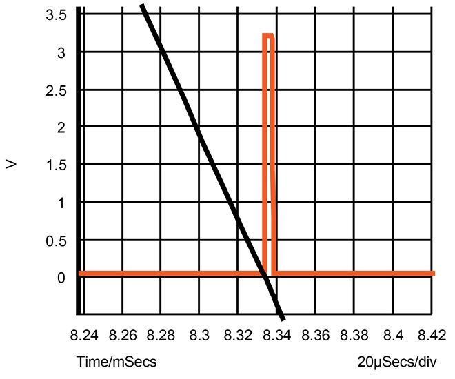
Figure 18-26. AC slope and output pulse.
With 110 V and Rext = 470 kW, the pulse is about 5 μs wide. You get the same width at 220 V if you double the value of Rext. The circuit works with a supply as low as 1.2 V.
CMOS Zero-Crossing Detector
The effect used to create the window does not work well in CMOS. Instead, we can employ two comparators. This circuit is illustrated in Figure 18-27.
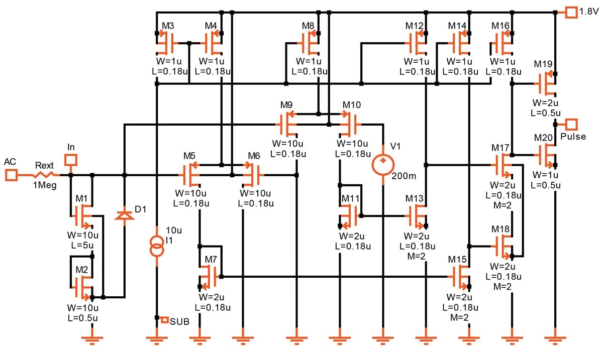
Figure 18-27. [click to enlarge] CMOS version of a zero-crossing detector.
In the circuit above, one comparator (M9, M10) is biased at about +200 mV and the other (M5, M6) at ground. Their outputs are then supplied to an AND gate (M17, M18), which drives the output.
The AC waveform is clamped in the positive direction by two diode-connected transistors (M1, M2) and in the negative direction by a substrate diode.
Since there is no base current, you could theoretically make Rext very large. However, you need to consider that the devices connected to the input (including the pad and the ESD protection device) have a small amount of capacitance. The time constant formed by the external resistor and this capacitance must be smaller than the desired pulse width.