Facebook
 Google
 GitHub
 Linkedin
Integrated Circuit Thermometers
The PTAT (proportional to absolute temperature) circuit has come up before during our discussion of current sources. It is remarkable that we can produce a voltage whose value is directly tied to the absolute temperature scale, with an accuracy that depends only on ratios and isn't affected by any process parameter. Figure 18-21 shows such a circuit.
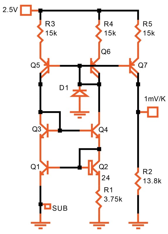
Figure 18-21. [click to enlarge] Thermometer with Kelvin scale.
Q1 through Q6 form a loop, started up by leakage alone. For safety, in case the models are not quite correct, a substantial junction (D1) can be added, which has more leakage current than any of the other devices.
The current in the loop is determined by the emitter ratios of Q2 to Q1 and R1. Recall the formula for the difference in the transistor base-emitter voltages:
$$\Delta V_{BE} ~=~ \frac {kT}{q} \ln \bigg( \frac {A_1 I_2}{A_2 I_1} \bigg)$$
The current mirror of Q5, Q6, R3, and R4 forces I1 and I2 to be identical. The area ratio of Q2 to Q1 is 24. Thus, ΔVBE amounts to roughly 83 mV at 300 K.
Since the temperature (T) is in Kelvin, the current increases linearly from zero at 0 K to 22 μA at 300 K. This current is then mirrored by Q7 and causes a voltage drop across R2. With the values chosen (and assuming perfect matching), the output voltage amounts to 1 mV per Kelvin. Note that any temperature coefficient or absolute variation in R1 is eliminated by a matching R2.
Although the design is relatively insensitive to power supply variation, accuracy is maximized by powering the thermometer from a reference voltage.
Matching is the all-important factor here. A ±1% resistor matching variation will result in an error of ±3 °C at room temperature. After adding the mismatch of VBE and hFE, you must expect a variation of up to ±5 °C untrimmed. With trimming, an accuracy of ±0.5 °C is possible.
Centigrade Thermometers
The centigrade (Celsius) scale is the same as the Kelvin one, except for the zero set to 273.16 K. So, all we need to do is create an offset voltage of 273.16 mV and read the temperature differentially. Similarly, we can create a Fahrenheit scale by increasing R2 by a factor of 1.8 and setting the offset to 459.67 mV.
Figure 18-22 shows a thermometer that uses the centigrade scale.
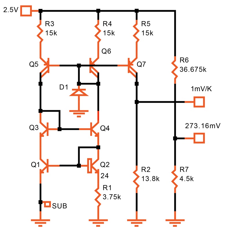
Figure 18-22. [click to enlarge] A thermometer with a Celsius scale.
R2 sets the slope, and R6 sets 0 °C. Trimming is straightforward:
- Trim R2 to read 293.16 mV at 20 °C at the upper terminal.
- Trim R6 to read 273.16 mV at the lower terminal (also at 20 °C).
CMOS Thermometers
As we saw in the Bandgap References chapter, substrate PNP transistors can be used in CMOS to create a ΔVBE. Figure 18-23 uses this approach to produce a Kelvin output. The current mirror is that of Figure 4-25.
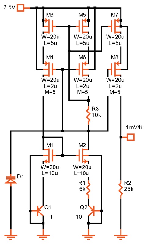
Figure 18-23. [click to enlarge] CMOS thermometer.
The untrimmed accuracy is somewhat worse in CMOS because of the poorer matching of the transistors for the same area. It's about ±7 °C at room temperature. You can improve this by using a larger emitter ratio for Q2/Q1 and larger devices overall.
Diode Thermometers
Finally, let's not forget the lowly diode. Its forward voltage has a predictable temperature dependence (about –2 mV/°C). As shown in Figure 18-24, we can use either an NPN or PNP bipolar transistor with the collector connected to the base to create a diode.
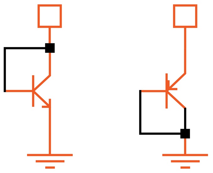
Figure 18-24. NPN and PNP diode thermometers.
The slope is subject to absolute variation and not quite as linear as that of a ΔVBE, but the device is nevertheless useful in some applications. For example, if you want to evaluate the temperature at a particular spot on an IC (such as next to a power device), use a diode-connected transistor and connect it to a small probing pad. You can then calibrate it before powering up the chip.