Facebook
 Google
 GitHub
 Linkedin
Microprocessor Internal Structure
Video Lectures created by Tim Feiegenbaum at North Seattle Community College.
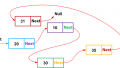
We're continuing with internal microprocessor structure. In examining the internal structure of a microprocessor, the elements that are needed to drive the address bus are … What we're looking at this point is the address bus. In the grand scheme of things here we have the microprocessor memory and the three buses. We're looking at the address bus and what is needed to drive the address bus? Well, first of all, we need a program counter. It is the origin of the memory address for the stored instructions. The number of stages is dependent upon the number of address lines.
In this case, we had the 1k of memory that we had previously discussed then this counter would have to be able to count up to 1024 to adequately address all of the addresses that are in this particular memory. As the counter counts, it is retrieving or writing instructions from or to memory. As this counter counts up it is retrieving instructions from memory. Now it is either retrieving them or it could be writing them to memory, in the case of the microprocessor writing data to memory in an output.
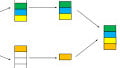
Additionally, the program counter tracks the execution of the program when branches are executed and it is necessary to return to a particular location in a program. As these commands, or these instructions, are executed by the processor the instructions may direct the counter to go to a specific branch or a specific number in the counter. The counter can be redirected to a count that is not sequential. The general process is output an address. It starts with an address on the address bus and this is a function of the counter. Read the instructions stored there. The microprocessor reads that instruction then it executes the instruction. Then increment the counter to the next address. The counter, in a methodical way, retrieves the addresses and feeds them to the processor for instruction.
Internal microprocessor structure. Program counter can be preset. To begin a program at the proper point an initial starting address is required. Initial values are preset and usually activated by pressing a reset pin on the microprocessor. This is if you have a PC and you press the reset button, or the start button, the computer starts up, but you might notice that it doesn't start up on the operating system. It starts by executing the information in ROM, it's called the BIOS. There's initial startup program and then the BIOS calls the operating system. The actual address is determined by the microprocessor manufacturer. When you press this preset button it goes to a specific address and that will be determined by the manufacturer of the microprocessor. For our discussion purpose, the preset address will be, we're just going to go to zero, zero, zero, zero, zero. The very beginning of memory, in fact, we might say zero, zero, zero, zero, one.
Data Bus Drivers
The data bus requires a device capable of both read and write, transmit and receive, or in and out operation. Data bus lines are bi-directional. A bi-directional bus driver or, more correctly, a tristate bi-directional bus driver is used to accomplish these functions. This has to do with the data bus. Let me jump back just a couple of slides here and we're talking about this right here at this point, the data bus. You'll notice that the address bus it's a one-way, control bus its one-way processor to memory, but data has to be able to flow in both directions. That's why we need some kind of device that will allow us to have this bi-directional control and we have something called a data bus driver.
Tri-State Drivers
Specifically, we're going to use a tristate bi-directional bus driver. Tri-state meaning that it has three different states and the three different states would be that you're moving data from memory to the processor, from the processor to memory, and then the third state is it's not doing anything.
First of all, we have two inputs going into this tri-state driver. We have the designation we saw as an in or out and what this simply means is data being sent to the processor or is it going out of the processor. Those two states will be determined by either a high or a low. Notice here if they're out that would be a low. You would move there from processor to memory and if it's a high you'd be moving data from memory to the processor. Now they only have the bus enable right here. It's low, notice the low comes in here, it's going to … both of these end gates will be disabled and that would create a high impedance state and that's where data isn't going anywhere. We're just stopped. The high allows data to move depending on the state of the in or out knots. If you have a high here it'll enable either input to output, but that will depend upon what we have on this input here. This function is controlled automatically by the computer. You don't need to go in and try to adjust this. This is just an automatic function.Now what we have here is the schematic from your multi-sim pack. This is figure 16-2 MSM. This simulation shows the bus enabled and input selected causing data to move on the bus driver to the microprocessor. Here we have this side would represent the microprocessor, over here would be memory, and what you'll note here is these little LED's are illuminated and what that is indicating is that data is moving from memory to the microprocessor. This would indicate here we have a high coming here. This end gate is enabled allowing data to move in this direction and the bus here is enabled. We have a high here going so this gate is enabled. We have data moving as an input. If this would have been in this position down here then we would have been moving data in the opposite direction and these LEDs over would be illuminated.
If this was in a low position right here the bus would be disabled. This would be the third state and there would be no data moving anywhere. We've looked at briefly at the subject of tri-state drivers. That concludes this particular lesson.