Facebook
 Google
 GitHub
 Linkedin
Positive Feedback
As we’ve seen, negative feedback is an incredibly useful principle when applied to operational amplifiers. It is what allows us to create all these practical circuits, being able to precisely set gains, rates, and other significant parameters with just a few changes of resistor values. Negative feedback makes all these circuits stable and self-correcting.
The basic principle of negative feedback is that the output tends to drive in a direction that creates a condition of equilibrium (balance). In an op-amp circuit with no feedback, there is no corrective mechanism, and the output voltage will saturate with the tiniest amount of differential voltage applied between the inputs. The result is a comparator:
With negative feedback (the output voltage “fed back” somehow to the inverting input), the circuit tends to prevent itself from driving the output to full saturation. Rather, the output voltage drives only as high or as low as needed to balance the two inputs’ voltages:
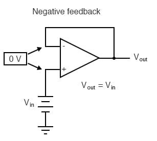
Whether the output is directly fed back to the inverting (-) input or coupled through a set of components, the effect is the same: the extremely high differential voltage gain of the op-amp will be “tamed” and the circuit will respond according to the dictates of the feedback “loop” connecting output to inverting input.
How Does Positive Feedback Work in an Op-Amp?
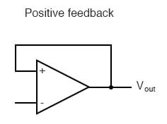
Another type of feedback, namely positive feedback, also finds application in op-amp circuits. Unlike negative feedback, where the output voltage is “fed back” to the inverting (-) input, with positive feedback the output voltage is somehow routed back to the noninverting (+) input. In its simplest form, we could connect a straight piece of wire from output to noninverting input and see what happens:
The inverting input remains disconnected from the feedback loop, and is free to receive an external voltage. Let’s see what happens if we ground the inverting input:
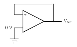
With the inverting input grounded (maintained at zero volts), the output voltage will be dictated by the magnitude and polarity of the voltage at the noninverting input. If that voltage happens to be positive, the op-amp will drive its output positive as well, feeding that positive voltage back to the noninverting input, which will result in full positive output saturation. On the other hand, if the voltage on the noninverting input happens to start out negative, the op-amp’s output will drive in the negative direction, feeding back to the noninverting input and resulting in full negative saturation.
What we have here is a circuit whose output is bistable: stable in one of two states (saturated positive or saturated negative). Once it has reached one of those saturated states, it will tend to remain in that state, unchanging. What is necessary to get it to switch states is a voltage placed upon the inverting (-) input of the same polarity, but of a slightly greater magnitude. For example, if our circuit is saturated at an output voltage of +12 volts, it will take an input voltage at the inverting input of at least +12 volts to get the output to change. When it changes, it will saturate fully negative.
How is Positive Feedback Useful?
An op-amp with positive feedback tends to stay in whatever output state its already in. It “latches” between one of two states, saturated positive or saturated negative. Technically, this is known as hysteresis.
Hysteresis can be a useful property for a comparator circuit to have. As we’ve seen before, comparators can be used to produce a square wave from any sort of ramping waveform (sine wave, triangle wave, sawtooth wave, etc.) input. If the incoming AC waveform is noise-free (that is, a “pure” waveform), a simple comparator will work just fine.
However, if there exist any anomalies in the waveform such as harmonics or “spikes” which cause the voltage to rise and fall significantly within the timespan of a single cycle, a comparator’s output might switch states unexpectedly:
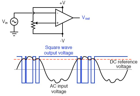
Any time there is a transition through the reference voltage level, no matter how tiny that transition may be, the output of the comparator will switch states, producing a square wave with “glitches.”
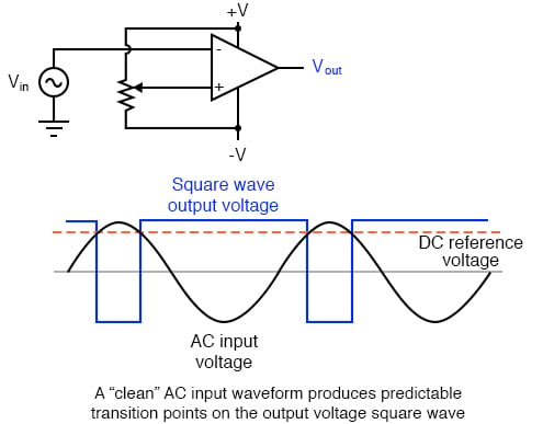
If we add a little positive feedback to the comparator circuit, we will introduce hysteresis into the output. This hysteresis will cause the output to remain in its current state unless the AC input voltage undergoes a major change in magnitude.
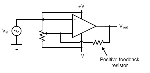
What this feedback resistor creates is a dual-reference for the comparator circuit. The voltage applied to the noninverting (+) input as a reference which to compare with the incoming AC voltage changes depending on the value of the op-amp’s output voltage. When the op-amp output is saturated positive, the reference voltage at the noninverting input will be more positive than before. Conversely, when the op-amp output is saturated negative, the reference voltage at the noninverting input will be more negative than before. The result is easier to understand on a graph:
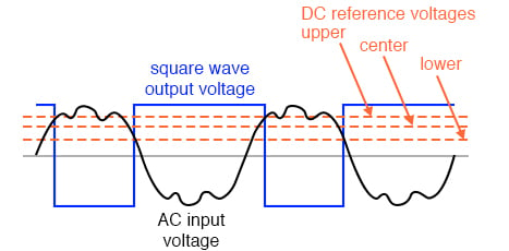
When the op-amp output is saturated positive, the upper reference voltage is in effect, and the output won’t drop to a negative saturation level unless the AC input rises above that upper reference level. Conversely, when the op-amp output is saturated negative, the lower reference voltage is in effect, and the output won’t rise to a positive saturation level unless the AC input drops below that lower reference level. The result is a clean square-wave output again, despite significant amounts of distortion in the AC input signal. In order for a “glitch” to cause the comparator to switch from one state to another, it would have to be at least as big (tall) as the difference between the upper and lower reference voltage levels, and at the right point in time to cross both those levels.
Another application of positive feedback in op-amp circuits is in the construction of oscillator circuits. An oscillator is a device that produces an alternating (AC), or at least pulsing, output voltage. Technically, it is known as an astable device: having no stable output state (no equilibrium whatsoever). Oscillators are very useful devices, and they are easily made with just an op-amp and a few external components.
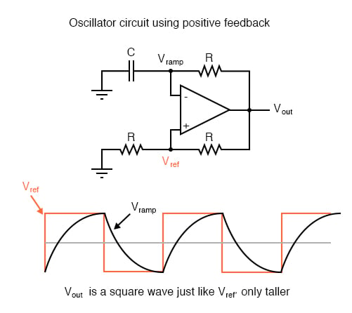
When the output is saturated positive, the Vref will be positive, and the capacitor will charge up in a positive direction. When Vramp exceeds Vref by the tiniest margin, the output will saturate negative, and the capacitor will charge in the opposite direction (polarity). Oscillation occurs because the positive feedback is instantaneous and the negative feedback is delayed (by means of an RC time constant). The frequency of this oscillator may be adjusted by varying the size of any component.
REVIEW:
- Negative feedback creates a condition of equilibrium (balance). Positive feedback creates a condition of hysteresis (the tendency to “latch” in one of two extreme states).
- An oscillator is a device producing an alternating or pulsing output voltage.
RELATED WORKSHEET: