
 Facebook
 Google
 GitHub
 Linkedin
Discrete Semiconductor Devices and Circuits
Active Loads in Amplifier Circuits
7 questions By Tony R. Kuphaldt
-
Question 4 of 7
The purpose of a current mirror circuit is to maintain constant current through a load despite changes in that load’s resistance:
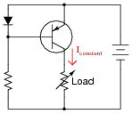
If we were to crudely model the transistor’s behavior as an automatically-varied rheostat - constantly adjusting resistance as necessary to keep load current constant - how would you describe this rheostat’s response to changes in load resistance?
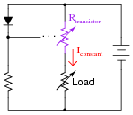
In other words, as Rload increases, what does Rtransistor do - increase resistance, decrease resistance, or remain the same resistance it was before? How does the changing value of Rtransistor affect total circuit resistance?
Reveal answerAs Rload increases, Rtransistor will decrease in resistance so as to maintain a constant current through the load and a constant Rtotal.
Notes:This model of current mirror transistor behavior, albeit crude, serves as a good introduction to the subject of active loads in transistor amplifier circuits. This is where a transistor is configured to operate as a constant-current regulator, then placed in series with an amplifying transistor to yield much greater voltage gains than what is possible with a passive (fixed resistor) load.
-
Question 5 of 7
An interesting technique to achieve extremely high voltage gain from a single-stage transistor amplifier is to substitute an active load for the customary load resistor (located at the collector terminal):

Usually, this “active load” takes the form of a current mirror circuit, behaving as a current regulator rather than as a true current source.
Explain why the presence of an active load results in significantly more voltage gain than a plain (passive) resistor. If the active load were a perfect current regulator, holding collector current absolutely constant despite any change in collector-base conductivity for the main amplifying transistor, what would the voltage gain be?
Reveal answerIf the active load were a perfect current regulator, the voltage gain of this single-stage amplifier circuit would be infinite (∞), because the Thévenin equivalent resistance for a current source is infinite ohms.
Notes:There is more than one way to comprehend this effect, and why it works as it does. One of the more sophisticated ways is to consider what the internal resistance of a perfect current source is: infinite. Ask your students how they contemplated this effect, and what means they employed to grasp the concept.
-
Question 6 of 7
Identify as many active loads as you can in the following (simplified) schematic of an LM324 operational amplifier circuit:
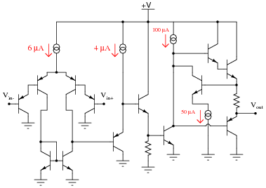
Reveal answerOf course, all the current sources are active loads, but there is one more at the lower-left corner of the schematic. I’ll let you figure out where it is!
Notes:Even if students do not yet know what an “operational amplifier” circuit is, they should still be able to identify transistor stages, configurations, and active loads. In this case, most of the active loads are obvious (as revealed by the current source symbols).
Don’t be surprised if some of your students point out that the differential pair in this opamp circuit looks “upside-down” compared to what they’ve seen before for differential pair circuits. Let them know that this is not really an issue, and that the differential pair works the same in this configuration.


