
 Facebook
 Google
 GitHub
 Linkedin
Basic Electricity
Basic Circuit Troubleshooting
18 questions By Tony R. Kuphaldt
-
Question 4 of 18
In this battery-switch-lamp circuit, the metal filament wire inside the lamp has burned up, so that it no longer forms an electrically continuous connection. In other words, the filament has failed “open.”
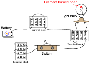
Of course, this means the lamp will not turn on, no matter what is done with the switch. It also means that most of the voltage measurements taken in the circuit will be the same as with a properly operating circuit. There is, however, one voltage measurement which will be different in the circuit with the burned-out filament than in a properly working circuit. Identify what pair or pairs of terminal block points this different voltage will be measured between, what switch state (ON or OFF) it will appear in, and what this different voltage measurement will actually be relative to the battery voltage.
Reveal answerWith the filament burned open, the only voltage measurement that will change in the circuit is the voltage across the switch when it is in the OFF state. Normally, the voltage across the switch in the OFF state will be full battery voltage, but now (with the open filament) it will be zero. I will let you determine which points in the circuit you may measure switch voltage between.
Notes:Be sure to ask your students why they think there will be no voltage dropped across the switch when it is OFF, now that the filament has burned open. It may be helpful to draw a schematic diagram (without all the terminal block points shown) as you discuss the reasoning with your students.
-
Question 5 of 18
In this circuit, where would you expect to measure full battery voltage (between what pairs of test points)?

Reveal answerYou should expect to measure full battery voltage with one test lead of your voltmeter touching any of the points along the top wire of the circuit (points A through E), and with the other test lead touching any of the points along the bottom wire of the circuit (points F through J).
Notes:This circuit provides an excellent opportunity to discuss the concept of “electrically common” points. Any points in a circuit directly connected together with wire are considered “electrically common” to each other: a voltage measurement referenced at any one of those points should be identical if referenced any of the other points as well.
-
Question 6 of 18
In this circuit, where would you not expect to measure significant voltage (between what pairs of test points)?

Reveal answerYou should not measure any significant voltage between any of the test points along the upper wire (A to B, A to C, A to D, etc.), nor between any of the test points along the lower wire (F to G, F to H, F to I, etc.). As a general rule, points in a circuit that are electrically common to each other should never have voltage between them.
Notes:The answer uses a concept which I’ve found to be very helpful in understanding electrical circuits: the idea of points in a circuit being electrically common to each other. Simply put, this means the points are connected together by conductors of negligible resistance. Having nearly 0 ohms of resistance between points assures insignificant voltage drop, even for large currents.
Conversely, if significant voltage is measured between points in a circuit, you can be assured that those points are not electrically common to each other. Engage your students in a discussion of electrical commonality and expected voltage drops:
- • If voltage is measured between two points in a circuit, are those two points electrically common to each other? Why or why not?
- • If no voltage is measured between two points in a circuit, are those two points electrically common to each other? Why or why not?





May I know the people who created these examples? through APA 6 or 7 format of citation?
Some good brain teasers. It was nice getting my head wrapped around the idea of getting voltage on a common side of a circuit (due to a break on that side) 🤠