Facebook
 Google
 GitHub
 Linkedin
Basic Electricity
Basic Ohmmeter Use
10 questions By Tony R. Kuphaldt
-
Question 4 of 10
Suppose a technician attempted to measure the resistance of resistor R5 on this printed circuit board:
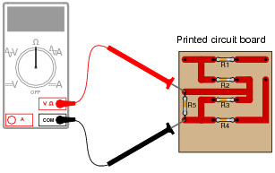
What is wrong with doing this?
Reveal answerR5 is not the only component whose resistance is being measured!
Follow-up question: what components on this printed circuit board may be measured with the ohmmeter without error?
Notes:This is very important for students to understand: the fact that the resistance of an individual component cannot be measured in a circuit, unless it is guaranteed that the ohmmeter’s measuring current passes through that component only. Here’s how to create your own ohmmeter.
-
Question 5 of 10
Shown here is a circuit constructed on a PCB (a “Printed Circuit Board”), with copper “traces” serving as wires to connect the components together:
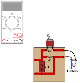
How would the multimeter be used to measure the resistance of the component labeled “R1”? Include these important points in your answer:
- •
- The configuration of the multimeter (selector switch position, test lead jacks)
- •
- The connections of the meter test leads to the circuit
- •
- The state of the switch on the PCB (open or closed)
Reveal answer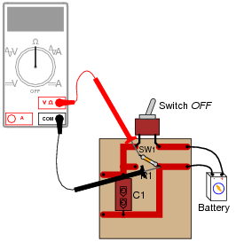
Notes:It is very important that students understand component resistance cannot be measured when the component is energized! In cases such as this, it is necessary to disconnect the component from the rest of the circuit so that only its resistance (and not any other components’ resistance) is measured. In other cases, though, it may be acceptable to leave the component in place to take a resistance measurement.
-
Question 6 of 10
A technician picks up a resistor with the following color bands:
Color code: Brn, Blk, Sil, Gld
Having forgotten the resistor color code, and being too lazy to research the color code in a book, the technician decides to simply measure its resistance with an ohmmeter. The value this technician obtains is 0.6 Ω.
What is wrong with the technician’s measurement?
Reveal answerThe resistance measurement is too high (it should be closer to 0.1 Ω) because the ohmmeter was not properly set up to compensate for test lead resistance.
Notes:Analog ohmmeters had to be “zeroed” prior to almost every measurement out of necessity, to give accurate measurements despite changes in internal battery voltage. Modern digital ohmmeters do not have this problem, but the lack of a “zeroing” procedure can lead to errors due to uncompensated test lead resistance. Your students should research the proper use of their own digital meters in this regard.