
 Facebook
 Google
 GitHub
 Linkedin
Basic Electricity
Basic Troubleshooting Strategies
15 questions By Tony R. Kuphaldt
-
Question 7 of 15
An electrician is troubleshooting a faulty light circuit, where the power source and light bulb are far removed from one another:

As you can see in the diagram, there are several terminal blocks (“TB”) through which electrical power is routed to the light bulb. These terminal blocks provide convenient connection points to join wires together, enabling sections of wire to be removed and replaced if necessary, without removing and replacing all the wiring.
The electrician is using a voltmeter to check for the presence of voltage between pairs of terminals in the circuit. The terminal blocks are located too far apart to allow for voltage checks between blocks (say, between one connection in TB2 and another connection in TB3). The voltmeter’s test leads are only long enough to check for voltage between pairs of connections at each terminal block.
In the next diagram, you can see the electrician’s voltage checks, in the sequence that they were taken:
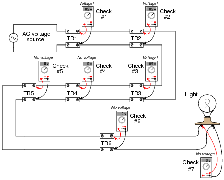
Based on the voltage indications shown, can you determine the location of the circuit fault? What about the electrician’s choice of steps - do you think the voltage measurements taken were performed in the most efficient sequence, or would you recommend a different order to save time?
Reveal answerThe fault is located somewhere between TB3 and TB4. Whether or not the electrician’s sequence was the most efficient depends on two factors not given in the problem:
- • The distance between terminal blocks.
- • The time required to gain access for a voltage check, upon reaching the terminal block location.
Follow-up question: describe a scenario where the given sequence of voltage readings would be the most efficient. Describe another scenario where a different sequence of voltage readings could have saved time in locating the problem.
Notes:One of the most common troubleshooting techniques taught to technicians is the so-called “divide and conquer” method, whereby the system or signal path is divided into halves with each measurement, until the location of the fault is pinpointed. However, there are some situations where it might actually save time to perform measurements in a linear progression (from one end to the other, until the power or signal is lost). Efficient troubleshooters never limit themselves to a rigid methodology if other methods are more efficient.
-
Question 8 of 15
This circuit is called a voltage divider, because it presents a fractional portion of the total voltage to the load:

(Of course, with no load connected, the voltage across the lower resistor would be precisely 6 volts. With the load connected, the parallel combination of load and 1 kΩ resistor results in an effective resistance of less than 1 kΩ on the lower half of the divider, resulting in a voltage of less than half the total supply voltage.)
Suppose that something goes wrong in this voltage divider circuit, and the load voltage suddenly falls to zero. A technician following the “divide-and-conquer” troubleshooting strategy begins by measuring voltage across the lower resistor (finding 0 volts), then measuring voltage across both resistors (finding 12 volts):
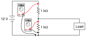
Based on these measurements, the technician concludes that the upper resistor must be failed open. Upon disassembling the divider circuit and checking resistance with an ohmmeter, though, both resistors are revealed to be in perfect operating condition.
What error did the technician make in concluding the upper resistor must have been failed open? Where do you think the problem is in this circuit?
Reveal answerThe technician wrongly assumed that an open (upper) resistor was the only possible fault that could have caused the observed voltage readings.
Notes:This is a common mistake students make when applying the “divide-and-conquer” method of troubleshooting: that whatever component(s) located between the point of good measurement and the point of bad measurement must be the source of the problem. While this simple reasoning may apply in finding “open” faults in long lengths of wire, it does not necessarily hold true for more complex circuits, as other faults may result in similar effects.
-
Question 9 of 15
This stereo system has a problem: only one of the two speakers is emitting sound. While the left speaker seems to be working just fine, the right speaker is silent regardless of where any of the stereo’s controls are set:

Identify three possible faults that could cause this problem to occur, and identify what components of the stereo system are known to be okay (be sure to count each cable as a separate component of the system!).
- Possible faults in the system:
- • Fault #1:
- • Fault #2:
- • Fault #3:
- Components known to be okay in the system:
- • Component #1:
- • Component #2:
- • Component #3:
Explain how you might go about troubleshooting this problem, using no test equipment whatsoever. Remember that the speaker cables detach easily from the speakers and from the amplifier.
Reveal answerComponents known to be okay include the left speaker, left speaker cable, and power cord for the amplifier. There are, of course, more known “good” components in this system that the three mentioned here, especially if you count discrete electronic components inside the amplifier itself.
Possible faults include the right speaker, the right speaker cable, and the right output channel of the amplifier. A very good way to determine which of these components is faulted is to swap cables and speakers between sides, but I’ll let you determine which component swaps test which components.
Notes:Swapping components can be a very powerful means of troubleshooting system problems where interchangeable components exist.



I have a question about troubleshooting.
As a technician you were asked to troubleshoot a pieces of electronic equipment which contains various electronic components . On opening the door of the cabinet, you perceived a pungent smell and in addition you observed the following:
1. There were some dirt and corrosion on the circuit board
2. One of the capacitor was discolored.
3. One of the leads of the transistor was broken..
Please I need an urgent answer please….