Facebook
 Google
 GitHub
 Linkedin
Basic Electricity
Electrical Connections
13 questions By Tony R. Kuphaldt
-
Question 7 of 13
How are connections made between the various wire ends of components inserted into printed circuit boards (“PCBs”)?
Reveal answerComponent wire ends are typically soldered onto strips of copper metal (called “traces”) affixed on the surface of the printed circuit board material, which itself is electrically insulating.

Notes:Be sure to have a variety of printed circuit boards available for your students to see and touch during discussion time. PCBs are widely used in all varieties of electronic applications, and are well suited for mass production manufacturing techniques.
-
Question 8 of 13
Suppose this circuit has a problem: the light bulb does not light up when the switch is turned “ON”. You suspect that a “bad” connection may exist in the circuit which is preventing current. How would you test the integrity of each connection using a voltmeter only?
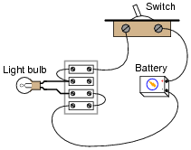
Reveal answerIf voltage is measured across any connection of two wires, that connection is definitely faulty.
Notes:It may be more difficult that it first appears to test for voltage across any single connection, if the wires are covered with insulation! Ask your students this question: if you test for voltage between two screws on a terminal strip, how many electrical connections are you actually measuring voltage across?
-
Question 9 of 13
Map the interconnections between holes in a typical solderless breadboard, also commonly known as a proto-board:

Reveal answer
Notes:“Mapping” the holes on a solderless breadboard is a fun exercise to do in class with ohmmeters (or any other form of continuity indicator).