Facebook
 Google
 GitHub
 Linkedin
Discrete Semiconductor Devices and Circuits
Insulated Gate Bipolar Transistors
5 questions By Tony R. Kuphaldt
-
Question 4 of 5
Draw a complete schematic diagram showing how this IGBT can be used to control a DC motor, at the command of the toggle switch:
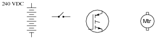
Note: the DC power supply voltage is 240 VDC, and the IGBT’s maximum gate-to-emitter control voltage is 20 volts!
Reveal answer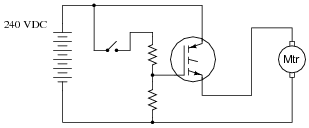
Follow-up question: calculate the values necessary for the two resistors shown, to provide a gate-to-emitter voltage of 10 volts, using 1/2 watt resistors.
Challenge question: why might it be a good idea to include a diode in the circuit, like this?

Notes:Ask your students what purpose the voltage divider serves. The first purpose should be obvious, as hinted in the “Note” at the end of the question. However, a second purpose is not so obvious. If the lower resistor were to fail open, the IGBT would turn on when the switch closes, but it would not turn off (at least not reliably) when the switch opens! Present this scenario to your students, and ask them to explain why this would happen.
Check your students’ math when they present resistor values. Do not be surprised if some students specify the resistor values such that the actual power dissipation runs right at 1/2 watt each! Use this as an opportunity to discuss component reliability versus power dissipation, and good engineering practices.
Regarding the challenge question, the diode is not there to provide a path for inductive “free-wheeling” current. Some of your students may suggest this as its purpose, but a close examination of polarity will show otherwise. The true answer to this question, in the context of a DC motor control circuit, has to do with the behavior of DC motors.
-
Question 5 of 5
Examine the schematic diagram for this photographic strobe light control system:

Explain its operation, and explain why an IGBT is a good transistor type for this application.
Reveal answerWhen the IGBT is turned on, the “trigger” transformer develops a high voltage pulse on the flash tube’s trigger wire, ionizing the xenon gas within and allowing a surge of current to pass between the tube’s main electrodes. Since the IGBT handles the tube’s main current as well, it is able to turn off the strobe as easily as it turned it on.
Notes:Even if students have never seen a strobe light circuit, they should at least be able to determine what happens when the transistor is immediately turned “on.” The fact that professional flash tubes require currents in excess of a hundred amps is not obvious from this schematic, so you should mention this fact in the discussion.
This schematic was adapted (simplified) from one found in a Fairchild IGBT application note (AN9006 - IGBT Application Note For Camera Strobe”).