Facebook
 Google
 GitHub
 Linkedin
Analog Integrated Circuits
Nonlinear OpAmp Circuits
17 questions By Tony R. Kuphaldt
-
Question 10 of 17
Design an op-amp circuit that divides one quantity (x) by another quantity (y) using logarithms. To give you a start on this circuit, I’ll provide the initial logarithmic op-amp modules in this diagram:
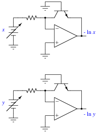
Note: it will be helpful for your analysis to write the mathematical expression at each op-amp output in your circuit, so you may readily see how the overall math function is constructed from individual steps.
Reveal answer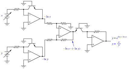
Notes:The circuit shown in the answer is a very common logarithmic construction: a log-ratio circuit, useful for many operations other than simple division. This question challenges students to put together the logarithm, antilogarithm, and differential op-amp circuits in a way that achieves the final design goal. Perhaps the most challenging aspect of this problem is managing the sign reversals.
-
Question 11 of 17
Find a datasheet for the AD538, an integrated circuit manufactured by Analog Devices. Then, read it carefully and explain how it is able to perform arithmetic functions such as multiplication, division, powers, and roots.
Reveal answerI’ll leave this up to you to research and to your classmates and instructor to discuss!
Notes:This question is destined for obsolescence, as one day the AD538 will no longer be manufactured. Until then, it is a fine piece of engineering, showcasing the power of logarithms as a computational aid in analog circuitry.
-
Question 12 of 17
Predict how the operation of this exponentiator circuit will be affected as a result of the following faults. Consider each fault independently (i.e. one at a time, no multiple faults):

- Resistor R1 fails open:
- Solder bridge (short) across resistor R1:
- Diode D1 fails open:
- Diode D1 fails shorted:
For each of these conditions, explain why the resulting effects will occur.
Reveal answer- Resistor R1 fails open: Vout saturates in the negative direction.
- Solder bridge (short) across resistor R1: Vout goes to zero volts.
- Diode D1 fails open: Vout goes to zero volts.
- Diode D1 fails shorted: Vout saturates in the negative direction.
Notes:The purpose of this question is to approach the domain of circuit troubleshooting from a perspective of knowing what the fault is, rather than only knowing what the symptoms are. Although this is not necessarily a realistic perspective, it helps students build the foundational knowledge necessary to diagnose a faulted circuit from empirical data. Questions such as this should be followed (eventually) by other questions asking students to identify likely faults based on measurements.