Facebook
 Google
 GitHub
 Linkedin
Basic Electricity
Overcurrent Protection
13 questions By Tony R. Kuphaldt
-
Question 7 of 13
Two 150-amp circuit breakers are connected in parallel to obtain a total ampacity of 300 amperes for an electric motor service. The system works just fine for several years, but then both breakers begin to spuriously trip:
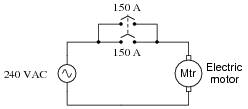
An electrician measures motor current using a clamp-on ammeter, and discovers the motor’s current is no more than 228 amperes at full mechanical load. Describe what might possibly be wrong that is causing both circuit breakers to trip.
Reveal answerOne of the circuit breakers has probably developed more resistance in its parallel branch than the other (contact resistance, resistance at the wire connection points, etc.). I will let you explain why this causes false trips.
Notes:This is a very practical problem, directly dealing with parallel resistances. Unfortunately, I have seen residential circuit breaker panels new from the manufacturer, equipped with paralleled breakers! Bad idea . . . baaaaaad idea.
Something worthwhile to note as a possible cause of the tripping is a spurious motor problem. Perhaps the circuit breakers are sharing current equally after all, but the motor is occasionally drawing more than 300 amps of current! Just because an electrician measured less than 300 amps at full load does not mean the motor never draws more than 300 amps. There may be another problem after all. Discuss this with your students, asking them how they would identify such a problem after having determined the two circuit breakers were doing their job correctly.
-
Question 8 of 13
A large industrial electric motor is supplied power through a pair of fuses:

One day the motor suddenly stops running, even though the switch is still in the “on” position. An electrician is summoned to troubleshoot the failed motor, and this person decides to perform some voltage measurements to determine whether or not one of the fuses has “blown” open before doing anything else. The measurements taken by the electrician are as such (with the switch in the “on” position):

- • Between A and ground = 120 volts AC
- • Between B and ground = 120 volts AC
- • Between C and ground = 120 volts AC
- • Between D and ground = 120 volts AC
Based on these measurements, the electrician decides that both fuses are still in good condition, and that the problem lies elsewhere in the circuit. Do you agree with this assessment? Why or why not?
Reveal answerSo long as the switch is still in the “on” position when these measurements were taken, one of the fuses could still be blown!
Follow-up question: what voltage measurement(s) would conclusively test the condition of both fuses?
Notes:I have actually seen an experienced electrician make this mistake on the job! Ask your students to explain how full voltage could be measured at points C and D, with respect to ground, even with one of the fuses blown.
-
Question 9 of 13
Explain the meaning of this fuse curve:

Reveal answerI’ll let you figure out what this graph means!
Notes:There is far more to the behavior of a fuse than a single current rating, as this “fuse curve” graph illustrates. Discuss with your students the significance of such a curve, and under what conditions a fuse can sustain a current greater than its rating.