 Facebook
 Google
 GitHub
 Linkedin
Designing a Quadrature Network Using an All-pass Filter
Quadrature networks convert a single input signal into two outputs with a 90-degree phase difference. This article explains how to design quadrature networks using all-pass filters.
Filters that alter the frequency response in a helpful way are widely known. However, less well-known are all-pass filters, which do not change the frequency response (which I believe should really be called ‘amplitude response’) but do change the phase of the applied signal. These filters have many uses, such as in musical effects, correcting delays in signal transmission, and controlling the crest factor (the ratio of peak value to the root-mean-square (RMS) value) of signals.
With simple all-pass filters, we can build quadrature networks, which, from a single input signal, produce two output signals with a nearly fixed phase difference at all frequencies within a specified range. These, too, can be used for special musical effects, but are also widely used in efficient modulation systems, such as single-sideband (SSB) and even independent sideband (ISB), in which an AM signal can carry two channels of information. Further historical applications include frequency-modulation of a crystal-controlled carrier and variable-speed operation of 3-phase motors.
This article will dive into how to design all-pass filters and quadrature networks. We'll also provide online design apps that use calculation methods beyond what is practicable with a pencil or even Microsoft Excel.
A Brief History of All-pass Filters
A serious study of all-pass filters seems to have started over 100 years ago. An early reference is a patent by R.V.L Hartley dated 1928 for SSB modulation [1]. The phrase ‘well-known’ was used in a seminal paper by R.B Dome, published in 1946 [2], unfortunately without a bibliography. Early studies were rather impenetrable because the underlying theory involves ‘elliptic functions’ arising from considering the circumference of an ellipse. In general, the values of these functions cannot be calculated exactly. A later study by W J Albertsheim and F R Shirley [3] broke through this difficulty by using certain symmetry properties of the functions to derive an algebraic design procedure that is quite practicable for a certain family of networks to be carried out in a spreadsheet.
In addition, all-pass filters can be made with RLC or even RC passive networks but require either a transformer or two opposite-polarity input signals. In contrast, filters using op-amps have a very simple cell, a ‘first-order filter,’ which is cascaded, often with only one component value change, to make filters of higher orders. This article will specifically study 2nd- and 4th-order filters, though more extended filters whose order is a power of 2 can be treated similarly. Keep in mind, however, that those of other orders can be significantly more difficult to design.
Although the circuits use op-amps, even modest devices like a TL072 can be used at quite high frequencies if the filters are based on simple high-pass filters so that high closed-loop gain is required at low frequencies rather than high frequencies.
What is an All-pass Filter?
We can imagine that an ‘all-stop’ filter is an open-circuit, so an ‘all-pass’ filter might be a short-circuit or a short piece of thick wire. But it’s not quite as simple as that. Signals have two properties, ‘amplitude (volts or amps) and phase, which indicate the timing of some identified point on a signal waveform concerning some stated ‘zero time’. Phase is meaningful only for sinusoidal signals, but since any signal can be represented as a set of sinusoidal signals, this is not a big problem.
An all-pass filter, then, has an output voltage (or current) equal to the input voltage (or current), but the output phase is changed or ‘shifted.’ It is very easy to make an all-pass filter with an op-amp, as shown in Figure 1.
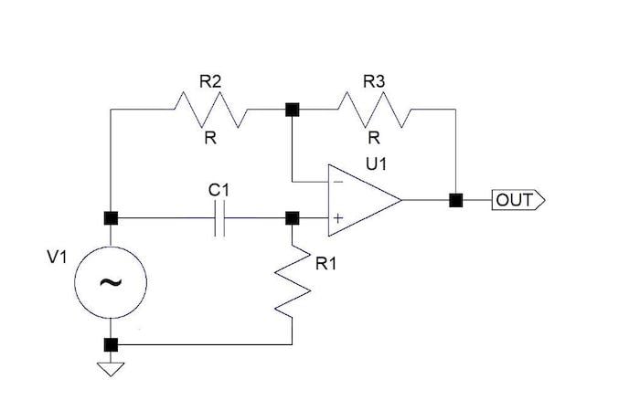
Figure 1. Example circuit diagram of a single-stage all-pass filter.
Please note that the DC supply for the op-amp is not shown. The equal resistors R2 and R3 make the output voltage at all frequencies equal to minus-one times the input voltage; however, the high-pass, C1 R1 network at the + input of the op-amp changes the output phase. Keep in mind that the capacitor and resistor could be changed around to make a low-pass network, but that means that high open-loop gain is required at high frequencies, which is not good.
To see how this works, recall that an op-amp has a high internal gain, so the output is produced by a tiny difference in the voltages at the two inputs. Since the phase of the + input signal is changed, thus the output signal phase changes.
The phase response of this circuit has two very fortunate properties. While the gain from the input to output is set to 1 by the equal resistors R, the gain through the filter-branch is 2 at high frequencies. This is a fundamental requirement for the filter to work correctly and results in the phase of the output varying twice as much as that of the CR filter, which, over a wide frequency range, varies from 0° to 90° so that the phase of the output varies from 0° to 180° (see Figure 2).

Figure 2. Phase shifts at the + input and the op-amp's output. The dotted lines are phase curves, as shown by the y-scale being in degrees. [click image to enlarge].
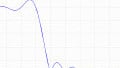
The other fortunate property is that over a certain frequency range (8:1 or more, depending on how much deviation is acceptable), the phase of the + input, and therefore that of the output, varies nearly inversely with the logarithm of frequency (see Figure 3). This is valuable for building quadrature networks.
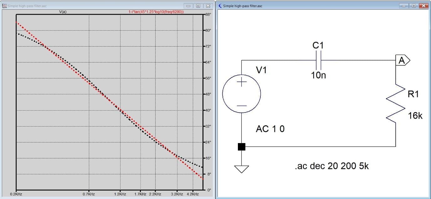
Figure 3. Linear relation between phase and log-scaled frequency [click image to enlarge].
In the above chart, the black line is the measured phase, and the red line is a straight-line approximation, showing a close fit.
It's possible to replace the passive high-pass filter with an active band-pass filter, but that makes quite a complex circuit and a step much too far for this article.
Building a 2nd-order Quadrature Network
Diving in, we can use pairs of all-pass filters to build quadrature networks, which, from an input signal, produce two signals, one with a 45 ° phase shift and one with a 135 ° shift, thus, giving a 90° phase difference between them. One signal is shifted sideways on the frequency scale with respect to the other. Figure 4 shows the simplest ‘second-order’ version.

Figure 4. A 2nd-order quadrature network [click to enlarge].
The only two component values that have to be calculated are R9 and R11. A way to do that is given in reference [3]; however, for a reason deeply embedded in advanced mathematics, it isn’t the best possible solution because the phase angle deviates only below 90°. Keep in mind, for many applications, the phase difference does not need (as is often assumed) to be precisely 90°; even a 10° error produces only small effects. This can easily be verified by connecting the outputs to an X-Y oscilloscope and observing how little the shape of the displayed circle varies with frequency. The solution shown is from a design app I used, QuadNet, which is a free offering by Jim Tonne.
In the charts, the black line is the phase at output A relative to the input, the red line is the phase at output B, and the yellow line is the phase difference between output A and output B.
Figure 5 shows the measured response of this network, built without special tight-tolerance components.

Figure 5. The measured response of a 2nd-order quadrature network
You can see how flat the frequency response is; however, the phase shift is within ±10° of 90° over the range of about 500 Hz to 2 kHz. To get a wider bandwidth, we need a higher-order network.
Building a 4th-order Quadrature Network
Figure 6 shows a 4th-order network that I designed in 1997 for a specific purpose—making phased array magnetic antennas for hearing-loop systems.
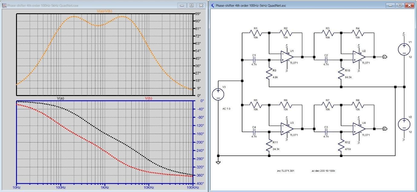
Figure 6. 4th-order network for 100 Hz to 5 kHz [click to enlarge].
In the chart, the black line is the phase at output A relative to the input, the red line is the phase at output B, and the yellow line is the phase difference between output A and output B.
Briefly, the way this works is that an audio signal current, mostly speech, is fed into a large loop of wire at floor level in a space, creating a magnetic field. This is picked up by a magnetic antenna (‘telecoil’) in a hearing aid, allowing the wearer to hear clearly. For covering large areas, and to prevent the magnetic field from spreading too far from where it is wanted, arrays of loops are used and fed with signals in phase-quadrature—thus, the need for a design.
In 1997, I didn’t have QuadNet, of course, so my original design was slightly off-optimum but quite close enough to have been widely used in real life.
Figure 7 shows the results from an actually measured network. The phase shift now is within ±10° of 90° over the range of about 90 Hz to 6 kHz, an improvement over the 2nd-order network.

Figure 7. The measured response of a 4th-order network
Wrapping up this project, we have demonstrated using simple all-pass filters to build quadrature networks that generate two output signals with a (nearly) fixed phase difference at all frequencies within a specified range. These find use in many applications that include creating musical effects and wireless communication modulation systems.
Bibliography
[1] US Patent #1,666,206 Modulation System, April 1928. The patent includes both a mathematical analysis and a bibliography.
[2] Wideband phase shift networks, R.B. Dome, Electronics, December 1946
[3] Computation methods for broad-band 90° phase-difference networks, W. J. Albertsheim and F. R. Shirley, IEEE Transactions on circuit theory, Vol. CT-16, No. 2, May 1969
The following are not cited in-text:
- D G C Luck, ‘Properties of some wide-band phase-splitting networks,’ Proc IRE June 1948
- S Darlington, ‘Realization of a constant phase difference,’ BSTJ 1950-01-01
- W Saraga, ‘The design of wide-band phase splitting networks,' Proc. IRE Vol 38 No. 7 July 1950
- S D Bedrosian, ‘Normalized design of 90° phase-difference networks,’ IRE Transactions on circuit theory, Vol. 7 Issue 2 June 1960
Related Content


And of course the same function done in digital processing generally involves computing a function which implements a Hilbert transform!