Facebook
 Google
 GitHub
 Linkedin
Using Analog Predistortion for RF Power Amplifier Linearization
We explore the basic concepts of analog predistortion for linearizing RF amplifiers and review some common implementations.
Modern communications systems employ signals that exhibit time-varying envelopes and phase angles. To handle these signals, transmitters require linear power amplifiers (PAs). However, they also require highly efficient power amplifiers. As we know, such amplifiers are inevitably nonlinear.
Fortunately, there are many ways to linearize the response of a PA. One approach, which we learned about in the previous article, is to find the distortion and subtract it from the PA’s output signal. This is known as feed-forward linearization.
Predistortion is another commonly used linearization technique. Instead of correcting the signal at the output, it places a nonlinear circuit before the power amplifier so that the combined response becomes linear. This circuit is called a predistorter or a predistortion linearizer.
Predistortion can be implemented using either analog or digital techniques. In this article, we’ll focus on analog predistortion. As we’ll see, both amplitude and phase linearization can be effectively accomplished using straightforward diode circuits. First, though, let’s examine the basic principles of predistortion more generally.
The Basics of Predistortion
For predistortion to work, it’s essential that we know the PA’s nonlinearity beforehand. We then adjust the input signal accordingly. The characteristics of the predistorter and the PA are mirror images about the desired linear response. This relationship is illustrated in Figure 1.

Figure 1. The predistorter's response is the inverse of the PA's nonlinear characteristic. Image used courtesy of Steve Arar
For example, consider a power amplifier that is expected to have unity gain. However, due to nonlinearity, its static characteristics vary according to the function y = g(x). In this scenario, the predistortion circuit should exhibit the inverse transfer characteristic (y = g-1(x)).
Compensating for a Compressive Characteristic
Figure 1 depicts a common scenario in which the PA demonstrates a compressive characteristic. To compensate, the predistortion circuit must expand the signal amplitude. This ensures that the predistorter/PA combination produces an amplified replica of the original input (Figure 2).

Figure 2. Expanding the signal amplitude counteracts the compressive characteristic of the power amplifier. Image used courtesy of Steve Arar
Note that the predistorter needs to suitably modify both the amplitude and phase of the input signal. At higher drive levels, predistorters are commonly designed to provide a positive amplitude deviation along with a negative phase deviation, similar to the predistorter response depicted in the above figure.
Predistortion Power and Frequency Considerations
The slope of the PA characteristic in Figure 1 is flat in the saturation region, requiring a predistortion curve with a vertical characteristic. For that reason, the saturation region of the PA can be challenging to compensate for using a predistorter. The predistortion technique is only effective at power levels that don’t cause the power amplifier to saturate.
This also means that the PA’s saturation determines the upper power limit of the combined predistorter/PA system. The peak power may be further constrained by the maximum expansion capability of the predistorter.
Predistortion can be implemented at the RF, IF, or baseband frequencies. In all cases, the difficulty lies in the determination and generation of the appropriate predistorter transfer function. The basic idea is still the same no matter where the predistortion is executed.
For instance, if the PA has a compressive characteristic, we apply an expansive characteristic to the input signal. That way, after undergoing the nonlinearity of the transmitter chain, the waveform reverts to its desired one.
Analog Predistortion
When the demands for linearity are moderate, an analog predistortion circuit can be used to linearize the power amplifier. These predistorters can be designed to compensate for both amplitude and phase nonlinearities.
Typically, analog predistortion circuits are attenuators with an expansive insertion loss characteristic. One way to implement this is to use two parallel signal paths: one with a linear gain, the other with a nonlinear compressive gain. This concept is illustrated in Figure 3.

Figure 3. Left: Block diagram of an analog predistorter. Right: Gain of the amplifiers and the predistorter. Image used courtesy of Steve Arar
The output is obtained by subtracting the nonlinear path’s output from that of the linear path. Due to its compressive nonlinear characteristic, the gain of the nonlinear amplifier reduces at large signal levels. As we see in Figure 3’s gain plot, this causes an increase in the predistorter’s overall gain. The increasing gain compensates for the gain roll-off of the following power amplifier.
Analog Predistortion Using Diode Circuits
Figure 4 shows how the nonlinear path in the above block diagram can be implemented with a diode limiter.

Figure 4. Using a diode limiter to implement the nonlinear path of the analog predistorter. Image used courtesy of Steve Arar
At low signal levels, the diodes don’t conduct, and the attenuation of the upper path is determined by the attenuator. At high drive levels, the diodes start to conduct, increasing the attenuation of this path. The phase shift and attenuator blocks can be used to adjust the response of the predistorter.
Linearizer With Series Diode and Parallel Capacitor
The diode-based method provides us with a systematic approach for implementing an analog predistorter. The literature features a variety of innovative circuits that use the nonlinear behavior of diodes and transistors to add gain expansion to the signal path. Figure 5 depicts a well-known example.
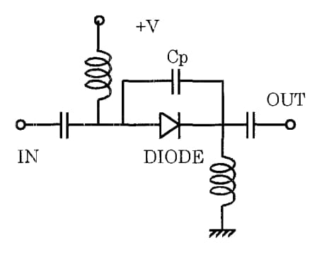
Figure 5. A diode-based predistorter circuit. Image used courtesy of K. Yamauchi
This linearizer consists of a diode connected in parallel with a capacitor. This diode-capacitor circuit is connected in series with the signal path. The predistorter also uses two RF chokes for DC feed and two DC-blocking capacitors.
At higher drive levels, the average current through the diode increases, reducing the dynamic resistance of the diode. Given that the diode is in series with the signal pathway, a reduction in its resistance at elevated input signal levels leads to a diminished insertion loss in the predistorter. The reduced insertion loss can also be thought of as gain expansion.
The parallel capacitor Cp allows us to adjust the phase shift of the predistorter. Figure 6 shows the response of the predistorter at 1.9 GHz for various values of the forward diode current.
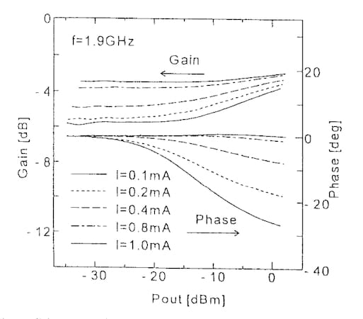
Figure 6. Measured response of the diode-based predistorter in Figure 5. Image used courtesy of K. Yamauchi
According to the measurements in Figure 6, the circuit produces positive amplitude deviation and negative phase deviation for forward currents from 0.1 mA to 1 mA. This circuit can therefore be used as a predistorter for PA linearization.
Linearizer With a Parallel Diode and Bias Feed Resistance
The same research team that proposed the above circuit also developed the predistorter in Figure 7.

Figure 7. A simple predistorter circuit positioned upstream of a power amplifier. Image used courtesy of K. Yamauchi
In this case, a parallel-connected diode with a bias feed resistor (Rb) is used to compensate for the distortion of a nonlinear PA. The linearizer incorporates two DC-blocking capacitors at its input and output. During small-signal operation, the diode is forward-biased. However, for a large-signal input, the current flowing through the diode is clipped around the trough of the current waveform.
This rectification increases the DC current through the diode. Since the DC current passes through the bias resistor Rb, a larger voltage drops across Rb as we increase the drive level. This, in turn, reduces the DC voltage across the diode. Therefore, the equivalent resistance of the diode increases with the signal level, resulting in an expansive amplitude response.
Figure 8 shows the response of this predistorter for three different supply voltages.

Figure 8. The calculated response of the predistorter in Figure 7 for three different values of Vcc. Image used courtesy of K. Yamauchi
The plot shows an expansive response. The circuit can therefore be used as a predistorter, at least over a limited dynamic range.
Applications
While the literature features a variety of analog predistortion circuits, they typically offer only slight enhancements in linearity. Also, they usually provide this improvement at a specific sweet spot that may exist for some part of the power range or bandwidth. Nevertheless, these circuits have the following advantages:
- Low cost.
- Low power consumption.
- Simplicity in implementation.
The modest gains in linearity they provide are beneficial for mobile radios. Additionally, they can sometimes be integrated with more complex system-level linearization techniques, such as feed-forward, to enhance the linearity of the error amplifier. Since diode-based linearization techniques provide the desired response over a limited power range, the choice of the right linearization circuit for a given amplifier depends on its power level.
This article is Part 2 in a series on linearization techniques and nonlinearity in RF systems. Below is a complete list of articles in this series:
- Introduction to the Feed-Forward Linearization of RF Power Amplifiers
- Using Analog Predistortion for RF Power Amplifier Linearization
- Improving RF Power Amplifier Linearity With Digital Predistortion
- Introduction to the Memory Effect in RF Power Amplifiers
- Using the 1 dB Compression Point to Characterize RF System Nonlinearity
- Understanding Intermodulation Distortion and the Third-Order Intercept Point in RF Systems
- A Guide to Calculating IM3 and IP3 for Nonlinear RF Circuits
- Understanding Dynamic Range and Spurious-Free Dynamic Range in RF Systems
- Understanding the Third-Order Intercept Point of a Cascaded System
- Dynamic Nonlinearity in RF Power Amplifiers: Insights From Two-Tone Testing