Facebook
 Google
 GitHub
 Linkedin
Analog Integrated Circuits
Active Filters
32 questions By Tony R. Kuphaldt
-
Question 4 of 32
Draw the Bode plot for an ideal low-pass filter circuit:

Be sure to note the “cutoff frequency” on your plot.
Reveal answer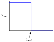
Follow-up question: a theoretical filter with this kind of idealized response is sometimes referred to as a “brick wall” filter. Explain why this name is appropriate.
Notes:The plot given in the answer, of course, is for an ideal low-pass filter, where all frequencies below fcutoff are passed and all frequencies above fcutoff are blocked. In reality, filter circuits never attain this ideal “square-edge” response. Discuss possible applications of such a filter with your students.
Challenge them to draw the Bode plots for ideal band-pass and band-stop filters as well. Exercises such as this really help to clarify the purpose of filter circuits. Otherwise, there is a tendency to lose perspective of what real filter circuits, with their correspondingly complex Bode plots and mathematical analyses, are supposed to do.
-
Question 5 of 32
Identify what type of filter this circuit is, and calculate its cutoff frequency given a resistor value of 1 kΩ and a capacitor value of 0.22 μF:

Calculate the impedance of both the resistor and the capacitor at this frequency. What do you notice about these two impedance values?
Reveal answerThis is a low-pass filter.
fcutoff = 723.4 Hz
Notes:Be sure to ask students where they found the cutoff frequency formula for this filter circuit.
When students calculate the impedance of the resistor and the capacitor at the cutoff frequency, they should notice something unique. Ask your students why these values are what they are at the cutoff frequency. Is this just a coincidence, or does this tell us more about how the “cutoff frequency” is defined for an RC circuit?
-
Question 6 of 32
Real filters never exhibit perfect “square-edge” Bode plot responses. A typical low-pass filter circuit, for example, might have a frequency response that looks like this:
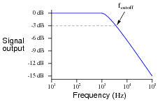
What does the term rolloff refer to, in the context of filter circuits and Bode plots? Why would this parameter be important to a technician or engineer?
Reveal answer“Rolloff” refers to the slope of the Bode plot in the attenuating range of the filter circuit, usually expressed in units of decibels per octave (dB/octave) or decibels per decade (dB/decade):
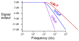
Notes:Point students’ attention to the scale used on this particular Bode plot. This is called a log-log scale, where neither vertical nor horizontal axis is linearly marked. This scaling allows a very wide range of conditions to be shown on a relatively small plot, and is very common in filter circuit analysis.