Facebook
 Google
 GitHub
 Linkedin
Analog Integrated Circuits
Active Filters
32 questions By Tony R. Kuphaldt
-
Question 19 of 32
Identify the function of this active filter:
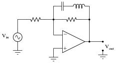
It is low pass, high pass, band pass, or band stop? Explain your answer.
Reveal answerThis is a band stop filter circuit.
Challenge question: how much voltage gain does this amplifier have at resonance? How much voltage gain does it have at f = 0 and f = ∞, if the two resistor values are equal?
Notes:If some students have difficulty analyzing the function of this circuit, ask them to identify the total impedance of a series-connected inductor and capacitor at resonance, then transfer that amount of impedance to the circuit to see what the effects will be at the resonant frequency.
-
Question 20 of 32
A very popular active filter topology is called the Sallen-Key. Two examples of Sallen-Key active filter circuits are shown here:
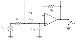
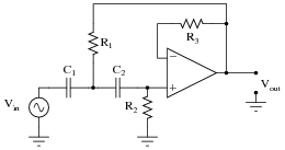
Determine which of these Sallen-Key filters is low pass, and which is high pass. Explain your answers.
Reveal answerThe first filter shown is low pass, while the second filter shown is high pass.
Challenge question: what is the purpose of resistor R3 in each circuit?
Notes:The word “topology” may be strange to your students. If any of them ask you what it means, ask them if they own a dictionary!
Like all the other active filter circuits, the fundamental characteristic of each filter may be determined by qualitative analysis at f = 0 and f = ∞. This is a form of thought experiment: determining the characteristics of a circuit by imagining the effects of certain given conditions, following through by analysis based on “first principles” of circuits, rather than by researching what the circuit’s intended function is.
Resistor R3 is actually not essential to the circuit’s operation, but is normally found in Sallen-Key filters anyway. If it makes the analysis of the circuit any simpler, tell your students they may replace that resistor with a straight wire in their schematic diagrams.
-
Question 21 of 32
In active and passive filter design literature, you often come across filter circuits classified as one of three different names:
- Chebyshev
- Butterworth
- Bessel
Describe what each of these names means. What, exactly, distinguishes a “Chebyshev” filter circuit from a “Butterworth” filter circuit?
Reveal answerEach of these terms describes a class of filter responses, rather than a particular circuit configuration (topology). The shape of the Bode plot for a filter circuit is the determining factor for whether it will be a “Chebyshev,” “Butterworth,” or “Bessel” filter.
Notes:I purposely omitted Bode plot examples for these three filter classifications. Presentation and examination of Bode plots is an appropriate activity for discussion time. Draw a set of Bode plot axes on the whiteboard, and then have students draw approximate Bode plots for each filter response, as determined from their research.