Facebook
 Google
 GitHub
 Linkedin
Analog Integrated Circuits
Active Filters
32 questions By Tony R. Kuphaldt
-
Question 25 of 32
Singers who wish to practice singing to popular music find that the following vocal eliminator circuit is useful:

The circuit works on the principle that vocal tracks are usually recorded through a single microphone at the recording studio, and thus are represented equally on each channel of a stereo sound system. This circuit effectively eliminates the vocal track from the song, leaving only the music to be heard through the headphone or speaker.
Operational amplifiers U1 and U2 provide input buffering so that the other opamp circuits do not excessively load the left and right channel input signals. Opamp U3 performs the subtraction function necessary to eliminate the vocal track.
You might think that these three opamps would be sufficient to make a vocal eliminator circuit, but there is one more necessary feature. Not only is the vocal track common to both left and right channels, but so is most of the bass (low-frequency) tones. Thus, the first three opamps (U1, U2, and U3) eliminate both vocal and bass signals from getting to the output, which is not what we want.
Explain how the other three opamps (U4, U5, and U6) work to restore bass tones to the output so they are not lost along with the vocal track.
Reveal answerI’ll let you figure out the function of opamps U4, U5, and U6 on your own!
Notes:Not only does this circuit illustrate a neat application of opamps, but it also showcases modular operational circuit design, where each opamp (and its supporting passive components) performs exactly one task.
-
Question 26 of 32
Predict how the operation of this active filter circuit will be affected as a result of the following faults. Consider each fault independently (i.e. one at a time, no multiple faults):

- Resistor R1 fails open:
- Capacitor C1 fails open:
- Solder bridge (short) across resistor R1:
- Solder bridge (short) across capacitor C1:
- Resistor R2 fails open:
- Resistor R3 fails open:
For each of these conditions, explain why the resulting effects will occur.
Reveal answer- Resistor R1 fails open: Filter circuit stops filtering, passes all frequencies.
- Capacitor C1 fails open: No signal output at all from the circuit.
- Solder bridge (short) across resistor R1: No signal output at all from the circuit.
- Solder bridge (short) across capacitor C1: Filter circuit stops filtering, passes all frequencies.
- Resistor R2 fails open: Voltage gain of circuit decreases to value of 1 (0 dB).
- Resistor R3 fails open: Filter circuit outputs square wave at all frequencies.
Notes:The purpose of this question is to approach the domain of circuit troubleshooting from a perspective of knowing what the fault is, rather than only knowing what the symptoms are. Although this is not necessarily a realistic perspective, it helps students build the foundational knowledge necessary to diagnose a faulted circuit from empirical data. Questions such as this should be followed (eventually) by other questions asking students to identify likely faults based on measurements.
-
Question 27 of 32
Predict how the operation of this active filter circuit will be affected as a result of the following faults. Consider each fault independently (i.e. one at a time, no multiple faults):
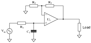
- Resistor R1 fails open:
- Capacitor C1 fails open:
- Solder bridge (short) across resistor R1:
- Solder bridge (short) across capacitor C1:
- Resistor R2 fails open:
- Resistor R3 fails open:
For each of these conditions, explain why the resulting effects will occur.
Reveal answer- Resistor R1 fails open: No signal output at all from the circuit.
- Capacitor C1 fails open: Filter circuit stops filtering, passes all frequencies.
- Solder bridge (short) across resistor R1: Filter circuit stops filtering, passes all frequencies.
- Solder bridge (short) across capacitor C1: No signal output at all from the circuit.
- Resistor R2 fails open: Voltage gain of circuit decreases to value of 1 (0 dB).
- Resistor R3 fails open: Filter circuit outputs square wave at all frequencies.
Notes:The purpose of this question is to approach the domain of circuit troubleshooting from a perspective of knowing what the fault is, rather than only knowing what the symptoms are. Although this is not necessarily a realistic perspective, it helps students build the foundational knowledge necessary to diagnose a faulted circuit from empirical data. Questions such as this should be followed (eventually) by other questions asking students to identify likely faults based on measurements.