Facebook
 Google
 GitHub
 Linkedin
Discrete Semiconductor Devices and Circuits
Class B BJT Amplifiers
12 questions By Tony R. Kuphaldt
-
Question 7 of 12
Two methods of biasing push-pull transistor pairs are shown here:

Which of these two methods is preferred, and why?
Reveal answerBiasing with diodes is preferred, because the bias voltage remains stable despite fluctuations in power supply rail voltages.
Notes:Ask your students what is special about a diode that provides just the right amount of bias voltage for the transistors.
-
Question 8 of 12
In a properly biased Class B amplifier circuit, how much voltage should be between the points A and B?

Reveal answer0 volts, at all moments in time!
Follow-up questions: explain how this fact may be useful in troubleshooting push-pull amplifier circuits, and also explain how this fact proves the amplifier has a voltage gain of unity (1).
Notes:Challenge your students to apply Kirchhoff’s Voltage Law to the “loops” around these two points, as such:
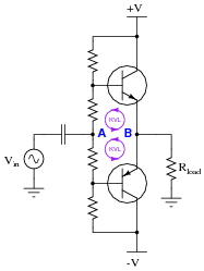
Knowing that the voltage between points A and B is zero, ask your students what the voltage drops must be across the biasing resistors. This question foreshadows the concept of a “virtual ground” in operational amplifier circuits. It is the idea that two or more points in a circuit may be held at the same potential without actually being connected together. In other words, the points are virtually common rather than being actually common with one another.
-
Question 9 of 12
One way to greatly boost the current gain (AI) of a Class B push-pull amplifier is to use Darlington pairs instead of single transistors:

The only problem with the Darlington pair amplifier circuit shown is that the original biasing network will no longer be sufficient. Unless something else is changed in this circuit, the amplifier will exhibit some crossover distortion.
Draw the necessary modifications to the circuit to properly bias the new transistors, and explain why these modifications are necessary.
Reveal answer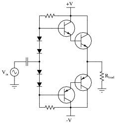
Notes:Ask your students to estimate the additional biasing voltage necessary with the two (new) transistors added to the circuit. How much biasing voltage, per transistor, was necessary with just two transistors in the circuit? Now that four transistors are in the circuit, how much more biasing voltage is necessary to avoid crossover distortion?