Facebook
 Google
 GitHub
 Linkedin
Discrete Semiconductor Devices and Circuits
Class B BJT Amplifiers
12 questions By Tony R. Kuphaldt
-
Question 4 of 12
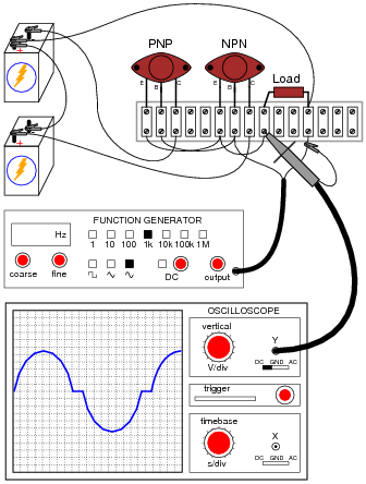
A student builds the following push-pull amplifier circuit, and notices that the output waveform is distorted from the original sine-wave shape output by the function generator:
Thinking that perhaps this circuit requires DC biasing, just like Class A amplifier circuits, the student turns on the “DC offset” feature of the function generator and introduces some DC voltage to the input signal. The result is actually worse:
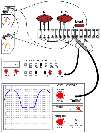
Obviously, the problem will not be fixed by biasing the AC input signal, so what causes this distortion in the output waveform?
Reveal answerI’ll give you a hint: this type of distortion is called crossover distortion, and it is the most prevalent type of distortion in Class B amplifier designs.
Challenge question: since this type of transistor amplifier is often referred to as a “push-pull” design, describe the cause of this distortion in terms of the transistors “pushing” and “pulling”.
Notes:Crossover distortion is fairly easy to understand, but more difficult to fix than the one-sided “clipping” distortion students are used to seeing in Class A amplifier designs. If you think it might help your students understand better, ask them how a push-pull amplifier circuit would respond to a slowly changing DC input voltage: one that started negative, went to zero volts, then increased in the positive direction. Carefully monitor the transistors’ status as this input signal slowly changes from negative to positive, and the reason for this form of distortion should be evident to all.
-
Question 5 of 12
What would happen to the output voltage waveform of this amplifier if the NPN transistor failed open between collector and emitter?
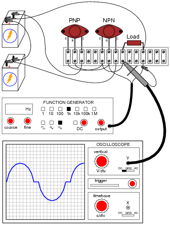
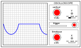
Reveal answerThe positive half of the waveform would be “missing”:
Notes:Ask your students to identify which transistor “sources” current to the load, and which transistor “sinks” current from the load, and the answer should be easy to understand.
-
Question 6 of 12
A simple yet impractical way to eliminate crossover distortion in a Class B amplifier is to add two small voltage sources to the circuit like this:

Explain why this solution works to eliminate crossover distortion.
Also, explain what practical purpose this push-pull amplifier circuit might serve, since its voltage gain is only 1 (0 dB).
Reveal answerEach voltage source biases its respective transistor to be at the brink of turning on when the instantaneous voltage of the input (Vin) is 0 volts.
Such amplifier circuits are typically used as voltage buffers: effectively diminishing the output impedance of the source (boosting its current sourcing/sinking capability) so that it may supply more current to a load.
Challenge question: how would you estimate the output impedance of such an amplifier circuit?
Notes:Ask your students to relate these bias voltage sources to the DC bias voltages previously seen in Class A amplifier designs. How much voltage do they think would be necessary to properly bias each transistor?