Facebook
 Google
 GitHub
 Linkedin
Basic Electricity
Parallel DC Circuits Practice Worksheet With Answers
24 questions By Tony R. Kuphaldt
-
Question 13 of 24
There are two well-known formulae for calculating the total resistance of parallel-connected resistances. One of these works only for two resistances, while the other works for any number of parallel resistances. Write these two formulae, and give examples of their use.
Reveal answer$$R_{parallel} = \frac{R_1R_2}{R_1+R_2}$$
$$R_{parallel} = \frac{1}{\frac{1}{R_1}+\frac{1}{R_2}+... \frac{1}{R_n}}$$
Notes:Although I typically use the lower formula exclusively in my teaching, the upper formula is often useful for situations where a calculator is not handy, and you must estimate parallel resistance.
-
Question 14 of 24
A quantity often useful in electric circuit analysis is conductance, defined as the reciprocal of resistance:
$$G= \frac{1}{R}$$
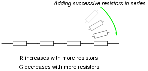
In a series circuit, resistance increases and conductance decreases with the addition of more resistors:
Describe what happens to total resistance and total conductance with the addition of parallel resistors:
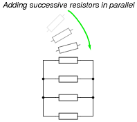
Reveal answerWhen successive resistors are connected in parallel, total resistance decreases while total conductance increases.
Follow-up question: what is the exact formula that describes total conductance in a network of parallel conductances?
$$G_{total}=???$$
Notes:Once students recognize the mathematical relationship between resistance and conductance \((G= \frac{1}{R})\), and they realize that parallel conductances add just like series resistances add, it is but a short exercise in algebra to develop the parallel resistance formula \((R_{parallel} = \frac{1}{\frac{1}{R_1}+\frac{1}{R_2}+... \frac{1}{R_n}})\).
-
Question 15 of 24
Explain, step by step, how to calculate the amount of current (I) that will go through each resistor in this parallel circuit, and also the voltage (V) dropped by each resistor:

Reveal answer- IR1 = 12 mA ; VR1 = 12 V
- IR2 = 5.45 mA ; VR2 = 12 V
- IR3 = 25.5 mA ; VR3 = 12 V
Follow-up question: trace the direction of current through all three resistors as well as the power supply (battery symbol). Compare these directions with the polarity of their shared voltage. Explain how the relationship between voltage polarity and current direction relates to each component’s identity as either a source or a load.
Notes:Students often just want to memorize a procedure for determining answers to questions like these. Challenge your students to not only understand the procedure, but to also explain why it must be followed.
Something your students will come to realize in discussion is that there is more than one way to arrive at all the answers! While some of the steps will be common to all calculation strategies, other steps (near the end) leave room for creativity.