Facebook
 Google
 GitHub
 Linkedin
Basic Electricity
Parallel DC Circuits Practice Worksheet With Answers
24 questions By Tony R. Kuphaldt
-
Question 19 of 24
What will happen in this circuit as the switches are sequentially turned on, starting with switch number 1 and ending with switch number 3?

Describe how the successive closure of these three switches will impact:
- • The voltage drop across each resistor
- • The current through each resistor
- • The total amount of current drawn from the battery
- • The total amount of circuit resistance “seen” by the battery
Reveal answerI won’t explain what happens when each of the switches is closed, but I will describe the effects of the first switch closing:
As the first switch (SW1) is closed, the voltage across resistor R1 will increase to full battery voltage, while the voltages across the remaining resistors will remain unchanged from their previous values. The current through resistor R1 will increase from zero to whatever value is predicted by Ohm’s Law (full battery voltage divided by that resistor’s resistance), and the current through the remaining resistors will remain unchanged from their previous values. The amount of current drawn from the battery will increase. Overall, the battery “sees” less total resistance than before.
Notes:One problem I’ve encountered while teaching the “laws” of parallel circuits is that some students mistakenly think the rule of “all voltages in a parallel circuit being the same” means that the amount of voltage in a parallel circuit is fixed over time and cannot change. The root of this misunderstanding is memorization rather than comprehension: students memorize the rule “all voltages are the same” and think this means the voltages must remain the same before and after any change is made to the circuit. I’ve actually had students complain to me, saying, “But you told us all voltages are the same in a parallel circuit!”, as though it were my job to decree perfect and universal Laws which would require no critical thinking on the part of the student. But I digress . . .
This question challenges students’ comprehension of parallel circuit behavior by asking what happens after a change is made to the circuit. The purpose of the switches is to “add” resistors from the circuit, one at a time, without actually having to insert new components.
-
Question 20 of 24
The circuit shown here is commonly referred to as a current divider. Calculate the voltage dropped across each resistor, the current drawn by each resistor, and the total amount of electrical resistance ßeen” by the 9-volt battery:
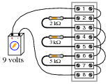
- • Current through the 2 kΩ resistor =
- • Current through the 3 kΩ resistor =
- • Current through the 5 kΩ resistor =
- • Voltage across each resistor =
- • Rtotal =
Can you think of any practical applications for a circuit such as this?
Reveal answer- • Current through the 2 kΩ resistor = 4.5 mA
- • Current through the 3 kΩ resistor = 3 mA
- • Current through the 5 kΩ resistor = 1.8 mA
- • Voltage across each resistor = 9 volts
- • Rtotal = 967.74 Ω
How much current is drawn from the battery in this circuit? How does this figure relate to the individual resistor currents, and to the total resistance value?
Notes:Some students may find the diagram hard to follow, and so they will find the task of analysis helped by drawing an equivalent schematic diagram for this circuit, with all terminal points labeled. I recommend you not suggest this solution immediately, but rather challenge your students to think of problem-solving techniques on their own. Surely, someone in the class will have thought of doing this, and the impact of such a suggestion coming from a peer is greater than if it came from you, the instructor.
Be sure to ask your students this question: “Why is this type of circuit commonly called a current divider?”
-
Question 21 of 24
There is a simple equation that gives the equivalent resistance of two resistances connected in parallel. Write this equation.
Secondly, apply this two-resistance equation to the solution for total resistance in this three-resistor network:

No, this is not a “trick” question! There is a way to apply a two-resistance equation to solve for three resistances connected in parallel.
Reveal answerRtotal = 25 Ω
In case you are still unsure of how to apply the “two-resistance” parallel equation to this network, I’ll give you a hint: this equation gives the equivalent resistance of two parallel-connected resistors. Examine this modified version of the original schematic diagram:
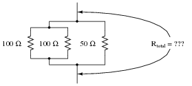
Notes:And who said technological work never involves creativity? This question challenges students to apply an equation to a problem that it is not ideally suited for. The basic principle used in the solution of the problem is very practical. It involves the substitution of an equivalent component value in place of multiple components, which is a problem-solving technique widely applied in electrical network analysis, as well as other forms of mathematical analysis.