
 Facebook
 Google
 GitHub
 Linkedin
Discrete Semiconductor Devices and Circuits
Thyristors
25 questions By Tony R. Kuphaldt
-
Question 19 of 25
The unijunction transistor, or UJT, is an interesting device, exhibiting hysteresis just like SCRs and TRIACs. Its schematic symbol is as follows:

One equivalent circuit diagram for the UJT uses a pair of transistors and a pair of resistors:
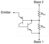
When the two base terminals of a UJT are connected across a source of DC voltage, the two base resistances (RB1 and RB2) form a voltage divider, splitting the applied voltage into lesser portions:

How much voltage, and of what polarity, must be applied to the emitter terminal of the UJT to turn it on? Write an equation solving for the magnitude of this triggering voltage (symbolized as VP), given RB1, RB2, and VBB.
Reveal answerVP ≈ VBB RB1 RB1 RB20.7 Follow-up question: how is the the standoff ratio defined for a UJT, and how might this equation be re-written to include it?
Notes:The standoff ratio is perhaps the most important UJT parameter, given the hysteretic switching function of this device. Writing the equation for trigger voltage (VP) and understanding the definition for standoff ratio requires that students remember the voltage divider formula from their studies in DC circuits:
VR = Vtotal ( R Rtotal) This question provides a good opportunity to review the operation of voltage divider circuits, and this formula in particular.
-
Question 20 of 25
A unijunction transistor with an intrinsic standoff ratio (η) of 0.8 is powered by a 15 volt DC source. Calculate the emitter voltage needed to “trigger” this UJT into its conductive state.

Reveal answerVP ≈ 12.7 volts
Notes:Nothing special here, just practice calculating the trigger voltage. Note to your students that the symbol for the intrinsic standoff ratio (η) is the Greek letter “eta,” which also happens to be used to symbolize efficiency.
-
Question 21 of 25
Describe what happens to the UJT as the potentiometer is slowly adjusted upward to provide a variable voltage at point A in this circuit, starting from 0 volts and ending at the trigger voltage VP:

Now describe what must be done to the potentiometer to cause the UJT to turn back off again.
Reveal answerThe UJT will remain in the nonconducting state as the potentiometer voltage increases from 0 volts, until it reaches VP. At that voltage, the UJT turns on and stays on. To turn the UJT off, the potentiometer must be adjusted back down in voltage until the current through point A decreases to a certain “dropout” value.
Notes:Ask your students to describe how hysteresis is exhibited by the UJT in this scenario.






Can someone please explain why do we need C1 capacitor in question 22 ? Circuit behaves exactly the same without it and I am confused about it’s purpose.