Facebook
 Google
 GitHub
 Linkedin
The Lateral PNP Transistor SPICE Model
For a lateral PNP transistor, the SPICE bipolar transistor model alone is woefully inadequate. This type of transistor produces a substrate current not only when it saturates, but also during normal operation. Neither of these are present in the SPICE model.
To correct this flaw, we need to use a subcircuit again. This time, only two additional transistors are required: one (Q21) to cause the substrate current at saturation and one (Q31) at normal operation. This subcircuit is illustrated in Figure 3-14.
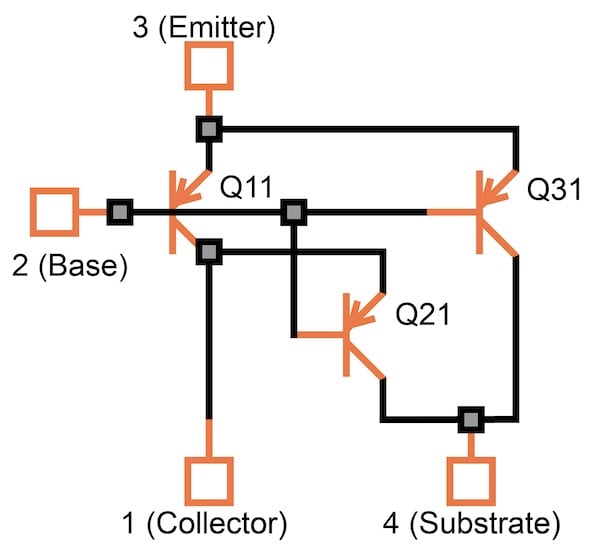
Figure 3-14. Equivalent circuit for a lateral PNP transistor.
The parameters of Q31 (particularly IS and BF) are chosen so that the substrate current is smaller than that of Q11 (generally about 20%). The model for this subcircuit looks like this:
.SUBCKT PNP1 1 2 3 4
QP11 1 2 3 QP1
QP21 4 2 1 QP2
QP31 4 2 3 QP3
.ENDS
And here are the models, again, for an arbitrary example of a 20 V process:
.MODEL QP1 PNP IS=1E-16 BF=89 VAF=35
+ IKF=1.2E-4 NK=0.58 ISE=3.4E-15 NE=1.6 BR=5
+ RE=100 RC=800 KF=1E-12 AF=1.2 XTI=5 ISC=1E-12
+ CJE=0.033E-12 MJE=0.31 VJE=0.75 CJC=0.175E-12
+ MJC=0.38 VJC=0.6 TF=5E-8 TR=5E-8
+ XTF=.35 ITF=1.1E-4 VTF=4 XTB=2.3E-1
.MODEL QP2 PNP IS=5E-15 BF=150 RE=100 TF=5E-8 XTI=5
.MODEL QP3 PNP IS=1E-18 BF=25 CJC=0.85E-12 MJC=0.42 VJC=0.6 XTI=5 RE=100