
 Facebook
 Google
 GitHub
 Linkedin
DC Electric Circuits
Ammeter Design
13 questions By Tony R. Kuphaldt
-
Question 10 of 13
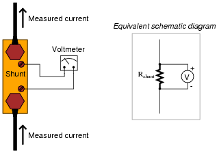
Shunt resistors used for precision current measurement always have four terminals for the electrical connections, even though normal resistors only have two:
Explain what would be wrong with connecting the voltmeter movement directly to the same two terminals conducting high current through the shunt resistor, like this:
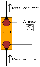
Reveal answerA two-wire shunt resistor connection will not be as accurate as a four-wire shunt resistor, due to stray resistance within the bolted connection between the wires and the body of the shunt resistor.
Challenge question: draw a schematic diagram showing all stray resistances within the two-wire shunt connection circuit, in order to clarify the concept.
Notes:Though a few fractions of an ohm of “stray” resistance may not seem like much, they are significant when contrasted against the already (very) low resistance of the shunt resistor’s body.
One of the conceptual difficulties I’ve encountered with students on numerous occasions is confusion over how much resistance, voltage, current, etc., constitutes a “significant” amount. For example, I’ve had students tell me that the difference between 296,342.5 ohms and 296,370.9 ohms is “really big,” when in fact it is less than ten thousandths of a percent of the base resistance values. Students simply subtract the two resistances and obtain 28.4 ohms, then think that “28.4” is a significant quantity because it is comparable to some of the other values they’re used to dealing with (100 ohms, 500 ohms, 1000 ohms, etc.).
Conversely, students may fail to see the significance of a few hundredths of an ohm of stray resistance in a shunt resistor circuit, when the entire resistance of the shunt resistor itself is only a few hundredths of an ohm. What matters most in problems of accuracy is the percentage or error, not the absolute value of the error itself. This is another practical application of estimating skills, which you should reinforce at every opportunity.
-
Question 11 of 13
Shunt resistors, being very low in resistance, are usually made from relatively large masses of metal. Their precise resistance is calibrated through a process known as trimming, where a technician takes a metal file and “trims” metal from the shunt conductor until the resistance reaches its correct value. This, of course, only works if the shunt resistor is intentionally manufactured with a resistance that is too low. Like the old carpenter’s joke goes, “I cut the board twice and it’s still too short!”
Being that shunt resistors have such incredibly low resistance values, how do we measure the resistance of a shunt with high accuracy during the “trimming” process? The resistance of a shunt is far too low for an average handheld or even benchtop ohmmeter to measure with precision, and specialized low-resistance ohmmeters such as the Kelvin Double Bridge are quite expensive. If you were given the task of trimming a shunt resistor for use in an ammeter, and you only possessed average pieces of test equipment, how could you do it?
Reveal answerBuild the ammeter and trim the shunt resistor in-place, with a calibrated amount of current through it.
Notes:The answer to this question is deceptively simple, yet extremely practical. Sure, it would be nice to have the best possible test and calibration equipment available to us at any time in our own laboratory, but we must be realistic. It is extremely important for your students that they engage in discussion on problems like this from a practical perspective. It is your task and your privilege as their instructor to bring your own experience into such discussions and challenge students with realistic obstacles to their (often) idealistic expectations.
-
Question 12 of 13
An important step in building any analog voltmeter or ammeter is to accurately determine the coil resistance of the meter movement. In electrical metrology, it is often easier to obtain extremely precise (“standard”) resistance values than it is to obtain equally precise voltage or current measurements. One technique that may be used to determine the coil resistance of a meter movement without need to accurately measure voltage or current is as follows.
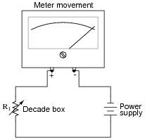
First, connect a decade box type of variable resistance in series with a regulated DC power supply, then to the meter movement to be tested. Adjust the decade box’s resistance so that the meter movement moves to some precise point on its scale, preferably the full-scale (100%) mark. Record the decade box’s resistance setting as R1:
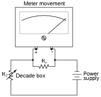
Then, connect a known resistance in parallel with the meter movement’s terminals. This resistance will be known as Rs, the shunt resistance. The meter movement deflection will decrease when you do this. Re-adjust the decade box’s resistance until the meter movement deflection returns to its former place. Record the decade box’s resistance setting as R2:
The meter movement’s coil resistance (Rcoil) may be calculated following this formula:
Rcoil = Rs R2(R1 − R2) Your task is to show where this formula comes from, deriving it from Ohm’s Law and whatever other equations you may be familiar with for circuit analysis.
Hint: in both cases (decade box set to R1 and set to R2), the voltage across the meter movement’s coil resistance is the same, the current through the meter movement is the same, and the power supply voltage is the same.
Reveal answerOne place to start from is the voltage divider equation, VR = VT R/RT applied to each circuit scenario:
Vmeter = Rcoil R1 RcoilVmeter = Rcoil || Rs R2 (Rcoil || Rs)Since we know that the meter’s voltage is the same in the two scenarios, we may set these equations equal to each other:
Rcoil R1 Rcoil= Rcoil || Rs R2 (Rcoil || Rs)Note: the double-bars in the above equation represent the parallel equivalent of Rcoil and Rs, for which you will have the substitute the appropriate mathematical expression.
Notes:This problem is really nothing more than an exercise in algebra, although it also serves to show how precision electrical measurements may be obtained by using standard resistors rather than precise voltmeters or ammeters.





Hi, Another solution for question 2 could be a parallel connection of the Anmeter with a serial resistor of 6000-400= 5600ohms in parallel with the 6 ohms resistor. Is that correct ?
have answr to immediate follow questions…...........prevent scrolloing.