Facebook
 Google
 GitHub
 Linkedin
Analog Integrated Circuits
Basic Operational Amplifiers
18 questions By Tony R. Kuphaldt
-
Question 13 of 18
A helpful model for understanding opamp function is one where the output of an opamp is thought of as being the wiper of a potentiometer, the wiper position automatically adjusted according to the difference in voltage measured between the two inputs:
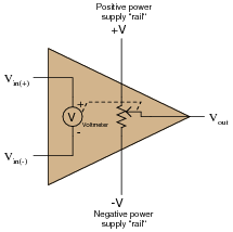
To elaborate further, imagine an extremely sensitive, analog, zero-center voltmeter inside the opamp, where the moving-coil mechanism of the voltmeter mechanically drives the potentiometer wiper. The wiper’s position would then be proportional to both the magnitude and polarity of the difference in voltage between the two input terminals.
Realistically, building such a voltmeter/potentiometer mechanism with the same sensitivity and dynamic performance as a solid-state opamp circuit would be impossible, but the point here is to model the opamp in terms of components that we are already very familiar with, not to suggest an alternative construction for real opamps.
Describe how this model helps to explain the output voltage limits of an opamp, and also where the opamp sources or sinks load current from.
Reveal answerThe output voltage of an opamp cannot exceed either power supply “rail” voltage, and it is these “rail” connections that either source or sink load current.
Follow-up question: does this model realistically depict the input characteristics (especially input impedance) of an opamp? Why or why not?
Notes:Students have told me that this opamp model öpened their eyes” to the behavior of opamp outputs, especially in situations where they would have otherwise expected an opamp to deliver an output voltage exceeding one of the rail voltages, or where the path of load current was critical. One of the common fallacies new students have about opamps is that output current somehow originates from current at one or both of the input terminals. This model also helps to shatter that illusion.
As a new instructor, I used to be shocked to see such misunderstandings in my students’ thinking. Surely from their previous experience with single-transistor amplifier circuits they knew the DC output voltage could never exceed the power supply rail voltages, right? Surely they understood that the current gain provided by multiple transistor stages effectively isolated output loading from the input(s), so that increased load at the output had negligible effect on input current, right? Well, not necessarily so!
The major reasons I am so adamant about having students expose their conceptions and thinking processes in a classroom discussion (rather than quietly listen to me lecture) is to be able to detect and correct these kinds of misunderstandings, and to be able to instill a sense of internal dialogue so that students learn to detect and correct the same kinds of misunderstandings on their own. Deep and critical thought does not seem to be a natural tendency in most human beings. To the contrary, a great many people seem perfectly content with meager and shallow comprehensions of the world around them, and must be prodded into assessing what they think they know. Pose questions to your students that challenge shallow thinking, that expose misunderstandings, and that force students to think more deeply than they are used to. In my opinion, building these metacognitive skills and habits is the very essence of higher education.
-
Question 14 of 18
In this circuit, an op-amp turns on an LED if the proper input voltage conditions are met:

Trace the complete path of current powering the LED. Where, exactly, does the LED get its power from?
Reveal answerThe arrows shown in this diagram trace “conventional” current flow, not electron flow:
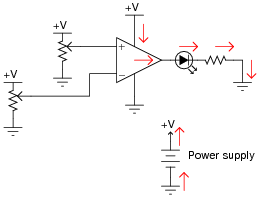
Notes:The important thing to note here is that the load current does not pass through either of the op-amp’s input terminals. All load current is sourced by the op-amp’s power supply! Discuss the importance of this fact with your students.
-
Question 15 of 18
Ideally, when the two input terminals of an op-amp are shorted together (creating a condition of zero differential voltage), and those two inputs are connected directly to ground (creating a condition of zero common-mode voltage), what should this op-amp’s output voltage be?

In reality, the output voltage of an op-amp under these conditions is not the same as what would be ideally predicted. Identify the fundamental problem in real op-amps, and also identify the best solution.
Reveal answerIdeally, Vout = 0 volts. However, the output voltage of a real op-amp under these conditions will invariably be “saturated” at full positive or full negative voltage due to differences in the two branches of its (internal) differential pair input circuitry. To counter this, the op-amp needs to be “trimmed” by external circuitry.
Follow-up question: the amount of differential voltage required to make the output of a real opamp settle at 0 volts is typically referred to as the input offset voltage. Research some typical input offset voltages for real operational amplifiers.
Challenge question: identify a model of op-amp that provides extra terminals for this “trimming” feature, and explain how it works.
Notes:In many ways, real op-amps fall short of their ideal expectations. However, modern op-amps are far, far better than the first models manufactured. And with such a wide variety of models to choose from, it is possible to obtain an almost perfect match for whatever design application you have, for a modest price.
If possible, discuss how “trimming” works in a real op-amp. If your students took the “challenge” and found some op-amp datasheets describing how to implement trimming, have them relate the connection of external components to the op-amp’s internal circuitry.