Facebook
 Google
 GitHub
 Linkedin
DC Electric Circuits
Time Constant Circuits
23 questions By Tony R. Kuphaldt
-
Question 22 of 23
Electromechanical relays are extremely useful devices, but they have their idiosyncrasies. One of them is a consequence of the fact that the relay’s coil acts as an inductor, storing energy in its magnetic field.
In the following circuit, a relay is used to switch power to a large electric motor, while being controlled by a light-duty pushbutton switch:
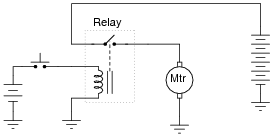
The problem here is every time the pushbutton switch is released, the contacts arc significantly. This happens because the inductor releases all of its stored energy as a high-voltage spark across the opening contacts. Inductive kickback is the phrase commonly used to describe this effect, and over time it will prematurely destroy the switch.
An electronics technician understands the nature of the problem and proposes a solution. By connecting a light bulb in parallel with the relay coil, the coil’s energy now has a safer place to dissipate whenever the pushbutton switch contacts open:
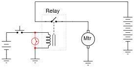
Instead of that stored energy manifesting itself as a high-voltage arc at the switch, it powers the light bulb for a brief time after the switch opens, dissipating in a non-destructive manner.
However, the addition of the light bulb introduces a new, unexpected problem to the circuit. Now, when the pushbutton switch is released, the relay delays for a fraction of a second before disengaging. This causes the motor to övershoot” its position instead of stopping when it is supposed to.
Explain why this happens, with reference to the LR time constant of this circuit before and after the addition of the lamp.
Reveal answerAdding the light bulb to this circuit increased the circuit’s time constant, causing the coil’s inductance to discharge at a slower rate.
Notes:This answer is rather minimal, if not obvious. Of course, if the relay takes longer to de-energize, and we were told this has something to do with time constants, then the time constant of the circuit must have increased. What is not so obvious is why τ increased. Discuss this with your students, and see what conclusions they reached.
-
Question 23 of 23
An electrical testing laboratory has designed and built a high-current ßurge” power supply for testing the effects of large electrical currents on certain types of components. The basic idea is that a bank of capacitors are charged to a high voltage by a DC power source (through a current-limiting resistor to protect the power source from overcurrent damage), then quickly discharged through a switch to the test load:

Due to the magnitude of the transient currents generated by the discharging capacitors, a mechanical switch (as suggested by the pushbutton symbol) is impractical. Instead, an air gap switch is constructed from two metal balls with a needle-point ïonizer” electrode between them. The ionizer electrode connects to a simple inductor/switch circuit that generates a high-voltage pulse sufficient to create a spark. The ionized air created in the spark provides a low-resistance path through the air which the 2000 volts from the capacitor bank can now traverse, thus completing the circuit for surge current between the capacitors and the test load:

Suppose this surge power supply circuit failed to work after several months of good service. Nothing happens any more when the pushbutton switch is pressed and released. No spark is heard or seen in the air gap, and the test load receives no surge of current.
A voltmeter placed (carefully!) in parallel with the capacitor bank indicates a full charge voltage of 2035 volts, which is within normal parameters. Based on this information, identify these things:
- •
- Two components in the circuit that you know must be in good working condition.
- •
- Two components in the circuit that could possibly be bad, and the mode of their failure (either open or shorted).
Reveal answerThe 2 kV DC power source must be functioning properly, as is its current-limiting resistor (Rlimit1). Possible failed components include:
- •
- Rlimit2 failed open
- •
- Inductor failed open or shorted
- •
- Pushbutton switch failed open or shorted
- •
- 24 VDC supply failed
- •
- Air gap switch ïonizing” needle tip burnt or otherwise worn
Follow-up question: explain how one would safely continue diagnostic measurements in a circuit such as this where there is much potential for electric shock and other hazards.
Notes:In addition to introducing the concept of an air gap switch and the notion of a ßurge” power supply, this question challenges students to envision practical problems and their respective diagnostic techniques.
It goes without saying that a circuit such as this is very dangerous, and its construction should not be attempted by anyone lacking a thorough understanding of its relevant hazards. Having said that, I will admit to having built one myself, simply to test the validity of an air gap switch for high-voltage, high-current, transient switching. Yes, the concept does work!