Facebook
 Google
 GitHub
 Linkedin
Digital Circuits
Encoders and Decoders
21 questions By Tony R. Kuphaldt
-
Question 16 of 21
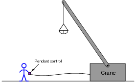
Suppose a crane has fifteen hydraulic solenoid valves controlling its motion:
- Tilt up (fast)
- Tilt down (fast)
- Tilt up (slow)
- Tilt down (slow)
- Turn left (fast)
- Turn right (fast)
- Turn left (slow)
- Turn right (slow)
- Cable up (fast)
- Cable down (fast)
- Cable up (slow)
- Cable down (slow)
- Bucket open (fast)
- Bucket open (slow)
- Bucket close (slow)
You are part of a team building a remote “pendant” control for this crane with fifteen buttons on it for controlling each of the fifteen solenoid valves. This control pendant connects to the main system by a multiconductor cable, but you really want to limit the number of conductors in this cable to keep it as light-weight as possible:
Draw a simple schematic diagram showing how a digital encoder and decoder circuit pair could be used to relay the same fifteen commands across fewer cable conductors, compared to if we used one conductor per pushbutton switch.
Reveal answer(Solenoid drive circuitry not shown):

Follow-up question: can you think of any disadvantages to this crane control strategy, compared to using a thicker cable where each pushbutton has its own dedicated conductor?
Challenge question: my choice of active-low inputs and outputs was not arbitrary. Explain why.
Notes:If time permits, you might want to ask students to sketch a “typical” solenoid drive sub-circuit, interposing the decoder outputs to DC (or AC!) solenoid valve coils. Several options are possible here, each with their own merits and drawbacks.
The challenge question is a good one to discuss, even if most students were not able to answer it on their own. It is not good enough to merely have a system that works - we must also have a system that is safe.
-
Question 17 of 21
The type 74HC154 integrated circuit is a standard TTL decoder, 4-line to 16-line. Its block symbol looks like this:

What do the “wedge” symbols next to the output lines represent? Also, what purpose do the \(\bar{G}\bar{1}\) and \(\bar{G}\bar{2}\) inputs serve, and why is there an ampersand character (&) next to them?
Reveal answerThe “wedge” symbols represent complementation in the IEEE/ANSI digital schematic convention, similar to “bubbles” placed near outputs or inputs of traditional logic gate symbols. Similarly, the ampersand character represents the AND function.
Perhaps the best way to determine what the \(\bar{G}\bar{1}\) and \(\bar{G}\bar{2}\) inputs do is to examine the truth table given in the datasheet for this integrated circuit.
Notes:Much may be learned from a good datasheet. This question, and others like it, prompts students to research manufacturer datasheets as a learning experience.
Note the truth table (likely) given in the datasheets your students collect. How are “irrelevant” states denoted in the truth tables? Ask your students what this means (especially with reference to the question regarding the strobe inputs).
-
Question 18 of 21
What is the purpose of a seven-segment decoder circuit? What is a “seven-segment” display, and why do we need a decoder circuit to drive it? Research the part number for a typical seven-segment decoder circuit (either CMOS or TTL).
Reveal answerSeven-segment displays are a very common numerical interface for digital electronic equipment:
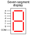
A special decoder circuit is needed to translate 4-bit BCD codes into the particular combinations of segment activations that represent decimal digits.
Follow-up question: what does the internal schematic of a typical seven-segment display look like? Is there just one type, or are there different types of seven-segment displays?
Notes:Be sure to ask your students to reveal the decoder datasheets they found. Once again, manufacturer datasheets contain a wealth of information, and your students will learn much by researching them.