Facebook
 Google
 GitHub
 Linkedin
Digital Circuits
Encoders and Decoders
21 questions By Tony R. Kuphaldt
-
Question 13 of 21
This “flash” ADC circuit has a problem. The output code jumps from 0000 to 1111 with just the slightest amount of input voltage (Vin). In fact, the only time it outputs 0000 is when the input terminal is slightly negative with reference to ground:
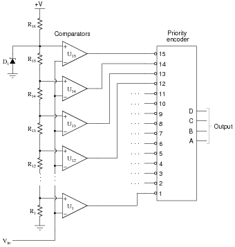
Identify at least two possible component faults that could cause this problem, and explain your reasoning in how you made the identifications.
Reveal answerOne possible fault is that resistor R16 has failed open, but this is not the only possibility.
Notes:Have your students explain their reasoning in class to you, so that you may observe their diagnostic thought processes.
-
Question 14 of 21
The truth table shown here is for a 4-line to 16-line binary decoder circuit:

For each of the sixteen output lines, there is a Boolean SOP expression describing its function. Just for example, write the Boolean expressions for output lines 5, 8, and 13.
Reveal answerOutput line 5: \({A}\bar{B}{C}\bar{D}\)
Output line 8: \(\bar{A}\bar{B}\bar{C}{D}\)
Output line 13: \({A}\bar{B}{CD}\)
Follow-up question: based on what you see here, what kind of logic gate circuitry is a decoder such as this comprised of? You don’t have to actually draw a schematic diagram, but just generally describe the circuitry necessary to implement sixteen different SOP expressions.
Notes:Nothing really complex or tricky here. Just a straightforward application of Boolean SOP expressions.
-
Question 15 of 21
The truth table shown here is for a 4-line to 16-line binary decoder circuit:

For each of the sixteen output lines, there is a Boolean SOP expression describing its function. Just for example, write the Boolean expressions for output lines 2, 11, and 14.
Reveal answerOutput line 2: \(\bar{A}{B}\bar{C}\bar{D}\)
Output line 11: \({AB}\bar{C}{D}\)
Output line 14: \(\bar{A}{BCD}\)
Follow-up question: based on what you see here, what kind of logic gate circuitry is a decoder such as this comprised of? You don’t have to actually draw a schematic diagram, but just generally describe the circuitry necessary to implement sixteen different SOP expressions.
Notes:Nothing really complex or tricky here. Just a straightforward application of Boolean SOP expressions.