Facebook
 Google
 GitHub
 Linkedin
DC Electric Circuits
Potentiometers
18 questions By Tony R. Kuphaldt
-
Question 13 of 18
Which way would you have to twist the potentiometer shaft in order to increase current through resistor R1, clockwise or counter-clockwise? Explain your answer.
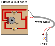
Reveal answerYou would have to twist the potentiometer shaft counter-clockwise.
Here’s a hint for those unfamiliar with the internal construction of rotary potentiometers:

Notes:This circuit is fairly self-explanatory, but getting the answer correct requires that you understand how a rotary potentiometer is constructed inside.
-
Question 14 of 18
This current divider circuit has a problem. The voltage between test points TP2 and TP1 varies with the potentiometer position, but the voltage between test points TP3 and TP1 remains at 0 volts no matter where the potentiometer is set:
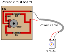
Identify the most likely fault which would account for these measurements.
Reveal answerThere is an “open” fault in resistor R2, or somewhere in series with R2 (bad solder connection, open trace, etc.).
Follow-up question: identify which direction of potentiometer shaft motion (clockwise or counter-clockwise) should increase the voltage between test points TP2 and TP1.
Notes:Discuss with your students how they determined the identity of the fault. Also, be sure to discuss the follow-up question with them: how to determine the proper direction to turn the potentiometer shaft in order to increase VTP2−TP1. It is important that your students realize how a 3/4 turn potentiometer works, and what to expect when the shaft is turned.
-
Question 15 of 18
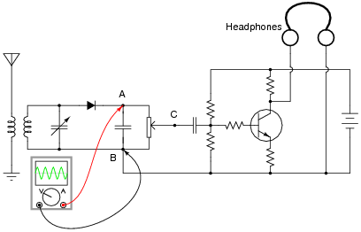
A radio technician is troubleshooting a problem in a simple AM receiver, using a voltage-measuring device called an oscilloscope. An oscilloscope is nothing more than a graphical voltmeter, indicating the “wave shape” of voltages that change rapidly over time. The problem with this radio is that no sound at all is heard in the headphones.
When checking for a voltage signal between points A and B in the circuit, a strong signal is obtained:
However, when checking between points C and B in the circuit, no signal is measured:
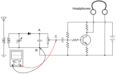
What do these voltage measurements indicate about the nature of the problem in the receiver circuit? Is there a general troubleshooting rule that may be drawn from this example? If so, what is it?
If possible, identify the precise nature of the failure.
Reveal answerThe fact that there is good signal before the potentiometer, and no signal afterward, indicates that the problem is somewhere between those two sets of signal measurement points (i.e. the potentiometer itself).
Notes:Do not worry if your students have not studied inductors, capacitors, diodes, transistors, amplifiers, or radio theory yet. This problem focuses on the potentiometer’s function, and that is all your students have to understand in order to determine an answer.
It is very important for electronics technicians to be able to isolate portions of circuits they do understand from portions they do not, and perform as much diagnostic work as they can based on what they know. For this reason, I believe it is a good practice to show beginning students problems such as this, where they are challenged to see beyond the complexity of the circuit, to focus only on those portions that matter. On the job, I was frequently challenged with troubleshooting large, complex systems that I had no hope of understanding the entirety of, but which I knew enough about to isolate the problem to sections I could repair proficiently.
Ask your students to identify where, exactly, they think the potentiometer could have failed in order to cause this particular problem. Not just any fault within the potentiometer will result in the same loss of signal!