Facebook
 Google
 GitHub
 Linkedin
Discrete Semiconductor Devices and Circuits
Rectifier Circuits
17 questions By Tony R. Kuphaldt
-
Question 4 of 17
What would this permanent-magnet DC motor do, if powered by the following circuit?
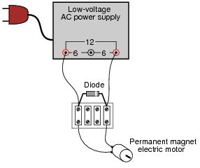
Reveal answerThe motor would spin in one direction, at least for a short moment in time. Then, something in the circuit (either the diode or the power supply) would fail due to excessive current!
Follow-up question: identify the polarity of the DC voltage between the motor terminals, during that brief period of time where all component are still functioning.
Notes:Ask your students why this circuit is self-destructive. If it functions as a rectifier for powering the DC motor for a short period of time, then why doesn’t it function that way for an indefinite period of time?
-
Question 5 of 17
Some inexpensive household lamps use a diode to achieve two-position light control (dim and bright):
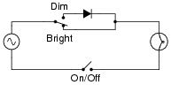
Explain how this circuit is able to make the light bulb glow brighter and dimmer.
Reveal answerWith the switch in the “dim” position, the light bulb only receives power for one-half of the AC cycle.
Follow-up question: does it matter which way the diode is oriented in the circuit? If we reversed its connections, would the light bulb behave any differently?
Notes:Although this circuit is not very complex, it reveals an application of diode rectification often overlooked: power control for non-polarized loads. Ask your students how the energy efficiency of a circuit like this compares to a rheostat (resistive) light dimming circuit.
-
Question 6 of 17
Trace the flow of all currents in this half of the AC cycle (note the polarity symbols near the transformer’s primary winding terminals):
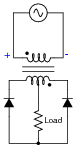
Now, trace the flow of all currents in the other half of the AC cycle (note the polarity symbols near the transformer’s primary winding terminals):
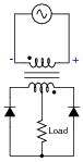
Also, determine the polarity of DC voltage across the load resistor.
Reveal answer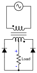
Notes:This question not only introduces a type of full-wave rectifying circuit, but it also serves as a good review of transformer action and winding phase markings. I have omitted diagrams showing direction of currents in this circuit, partly because they may be ascertained by way of the load resistor’s voltage polarity (shown in the answer), and partly because I’d rather not have to choose between giving an answer in conventional flow notation versus electron flow notation.