Facebook
 Google
 GitHub
 Linkedin
Discrete Semiconductor Devices and Circuits
Rectifier Circuits
17 questions By Tony R. Kuphaldt
-
Question 7 of 17
In this rectifier circuit, the output voltage is less than half of the secondary winding’s rated voltage (12 volts). Why is this?

Also, determine whether this is a half-wave or a full-wave rectifier circuit, and explain your answer.
Reveal answerOnly one-half of the secondary winding powers the load at any given time.
This is a full-wave rectifier circuit.
Challenge question: what would have to change in this circuit to make it a half-wave rectifier?
Notes:If this question is confusing to some students, take time to discuss the directions of all currents in the circuit through both halves of the AC cycle. Then, the answer should be apparent.
-
Question 8 of 17
A very common form of full-wave rectifier circuit is the bridge rectifier. Typically, it is drawn as a “diamond” of four diodes:

Draw the connections in this illustration to form a bridge rectifier circuit, receiving power from the transformer and delivering power to the light bulb:

Reveal answer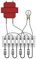
Follow-up question: draw the direction of currents through the bridge rectifier for each half-cycle of the AC power source, and determine the DC voltage polarity across the light bulb terminals.
Notes:Realistic connection problems such as this are much easier to solve in the presence of a schematic diagram. If you have students who struggle with this question, make sure they take the time to draw a schematic first. Finding a schematic diagram of a full-wave bridge rectifier circuit to copy is no challenge at all. As a rule, I do not offer assistance to students with questions until they have at least taken this first step, because so often they end up answering their own questions in the process of drawing a schematic diagram!
-
Question 9 of 17
Determine the approximate amount of voltage that each voltmeter in this circuit will indicate:
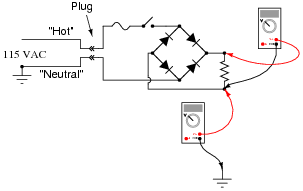
Reveal answerNote: the voltage readings shown by the voltmeters are approximate only!

Challenge question: how could the 58 volts from (-) to ground be eliminated, so as to permit grounding of the (-) output terminal?
Notes:Direct rectification of a grounded AC power source results in significant voltage being dropped between either DC output conductor and ground. Ask your students what kinds of problems might be caused by this effect. How about safety? Ask them if they think 58 volts presents a safety hazard.
In answer to the challenge question, what is needed here is some kind of electrical isolation. There is more than one answer to this problem, but definitely one solution that is more popular than the others.