Facebook
 Google
 GitHub
 Linkedin
Discrete Semiconductor Devices and Circuits
Rectifier Circuits
17 questions By Tony R. Kuphaldt
-
Question 10 of 17
A technician decides to measure the output voltage of a bridge rectifier circuit using an oscilloscope. This particular bridge rectifier is the front-end of a switching power supply circuit, and directly rectifies the incoming 120 volt AC power, with no transformer:
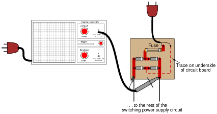
However, the technician is surprised to find that the fuse blows every time she turns the power on to the circuit. When the oscilloscope is disconnected from the circuit, the fuse does not blow, and everything works fine. What is wrong? Why does the oscilloscope cause a fault in the circuit?
Here is another interesting piece of information: if just the probe tip is touched to one of the rectifier circuit’s output terminals, the oscilloscope shows a half-wave rectified waveform, without the ground clip being connected to anything!
Reveal answerThe oscilloscope’s “ground” clip (the alligator-style clip that serves as the second electrical connection point on the probe) is electrically common to the metal chassis of the oscilloscope, which in turn is electrically common with the safety ground conductor of the 120 volt AC power system.
Notes:The answer given here does not reveal everything. The student still must determine why grounding one of the rectifier circuit’s output terminals results in a ground fault that blows the fuse. The observation of a half-wave signal with just the probe tip touching the circuit is the big hint in this question.
-
Question 11 of 17
Power rectifier circuits are often classified according to their number of phases, ways, and pulses. Match the following rectifier circuits to the Phase/Way/Pulse labels given in this illustration:

Reveal answer
Notes:The meaning of these labels can be confusing, so be sure to discuss them thoroughly with your students. Have them tell you what “Phases,” “Ways,” and “Pulses” mean, using their own words.
-
Question 12 of 17
Bipolar transistors are extremely useful devices, allowing a small electric current to control the flow of a much larger electric current:

These devices would be even more useful to us if they were able to control alternating current (AC), but they cannot. Bipolar transistors are polarized (one-way-only) devices.
This fact does not prevent us from using bipolar transistors to control AC. We just have to be clever about how we do it:

Explain how this circuit functions. How is the transistor (a DC-only device) able to control alternating current (AC) through the load?
Reveal answerThe four-diode bridge rectifies the AC load’s current into DC for the transistor to control.
Notes:Usually, rectifier circuits are thought of exclusively as intermediary steps between AC and DC in the context of an AC-DC power supply. They have other uses, though, as demonstrated by this interesting circuit!
It should be of no consequence if students have not yet studied transistors. In fact, it is a good thing to give them a very brief introduction to the function of a previously unknown component and then have them examine a circuit (the rest of which they should understand well) to ascertain an overall function. This is sometimes called the “Black Box” approach in engineering, and it is necessary when working around state-of-the-art electronic equipment, where you are practically guaranteed not to understand the inner workings of every subsystem and component.