
 Facebook
 Google
 GitHub
 Linkedin
Basic Electricity
Simple Circuits
41 questions By Tony R. Kuphaldt
-
Question 7 of 41
Shown here is a circuit constructed on a PCB (a “Printed Circuit Board”), with copper “traces” serving as wires to connect the components together:
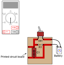
How would the multimeter be used to measure the voltage across the component labeled “R1” when energized? Include these important points in your answer:
- • The configuration of the multimeter (selector switch position, test lead jacks)
- • The connections of the meter test leads to the circuit
- • The state of the switch on the PCB (open or closed)
Reveal answer
The test lead connections (to the circuit) shown are not the only correct answer. It is possible to touch the test leads to different points on the PCB and still measure the voltage across the resistor (component labeled R1). What are some alternative points on the PCB where the voltage across R1 could be measured?
Notes:Many multimeters use “international” symbols to label DC and AC selector switch positions. It is important for students to understand what these symbols mean.
The test lead connections (to the circuit) shown are not the only correct answer. It is possible to touch the test leads to different points on the PCB and still measure the voltage across the resistor (R1). However, if there are poor connections on the circuit board (between component leads and copper traces), measuring voltage at points on the circuit board other than directly across the component in question may give misleading measurements. Discuss this with your students.
-
Question 8 of 41
What difference will it make if the switch is located in either of these two alternate locations in the circuit?


Reveal answerThe choice of switch locations shown in the two alternate diagrams makes no difference at all. In either case, the switch exerts the same control over the light bulb.
Notes:This is a difficult concept for some students to master. Make sure they all understand the nature of electrical current and the importance of continuity throughout the entire circuit. Perhaps the best way for students to master this concept is to actually build working battery-switch-lamp circuits. Remind them that their “research” of these worksheet questions is not limited to book reading. It is not only valid, but preferable for them to experiment on their own, so long as the voltages are low enough that no shock hazard exists.
One analogy to use for the switch’s function that makes sense with the schematic is a drawbridge: when the bridge is down (closed), cars may cross; when the bridge is up (open), cars cannot.
-
Question 9 of 41
Identify the following types of switches, according to the number of “poles” and “throws” each switch has:

Reveal answer
Notes:Switches come in all types and sizes, and it is important for students to recognize certain common switch types, both by name and by schematic symbol.


