Facebook
 Google
 GitHub
 Linkedin
Basic Electricity
Simple Circuits
41 questions By Tony R. Kuphaldt
-
Question 22 of 41
Suppose this battery and light bulb circuit failed to work:

Using a voltmeter, a technician measures 0 volts between the points C and H. The result of this single measurement indicates which half of the circuit there is a definite problem in. What would you recommend as the next voltmeter measurement to take in troubleshooting the circuit, following the same “divide in half” strategy?
Reveal answerTo “divide the circuit in half” again, measure voltage between points B and G.
Notes:Some troubleshooters refer to this strategy as “divide and conquer,” because it divides the possibilities of fault location by a factor of 2 with each step.
It is important to realize in situations such as this that no determination of faultlessness in the circuit has been made yet. By measuring 0 volts between points C and H, we know there is a definite problem in the left half of the circuit, but we have by no means “cleared” the right half of the circuit of any fault. For all we know, there may be faults in both halves of the circuit! Only further investigation will reveal the truth.
-
Question 23 of 41
Suppose this battery and light bulb circuit failed to work:

Using nothing but a voltmeter, a technician measures voltage between the following sets of points:
- • Between A and C: 0 volts
- • Between D and G: 12 volts
- • Between E and J: 0 volts
- • Between B and E: 12 volts
From these voltage measurements, what can you tell about the condition of the battery, wiring, and light bulb? Be as specific as you can.
Challenge question: identify which of the four measurement are unnecessary in determining the precise location of the fault in this circuit.
Reveal answerBased on these measurements, we are able to determine that the battery’s voltage is 12 volts, that the light bulb has good continuity, and that there is a single break in the circuit between points D and E.
Challenge answer: the two “0 volt” measurements are unnecessary in determining the location of the fault in this circuit.
Notes:Scenarios such as this are excellent for group discussion, encouraging students to think critically about the data and to apply their practical knowledge of electricity to a realistic problem.
-
Question 24 of 41
The circuit shown here is called a “bridge rectifier,” and its purpose is to convert alternating current (from the “power-supply” unit) into direct current. Suppose you were instructed to check the continuity of the switch (SW1) mounted on the printed circuit board. What would be a fast and effective way of testing this switch’s continuity (ideally, without removing the switch from the circuit board)?
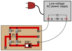
Reveal answerDisconnect the power supply from the circuit board (only one wire need be disconnected), and then use an ohmmeter to measure continuity across the switch terminals when in the ÖN” position and when in the ÖFF” position. Incidentally, this is not the only way to check the switch’s continuity, but it is the most direct.
Notes:Challenge your students to think of other methods which could be used to check the switch’s continuity. There is often more than one way to perform a certain check of component function, if you are knowledgeable in electrical theory and creative in your use of test equipment!