Facebook
 Google
 GitHub
 Linkedin
Basic Electricity
Simple Circuits
41 questions By Tony R. Kuphaldt
-
Question 28 of 41
Examine this schematic diagram:

Now, without moving the following components, show how they may be connected together with wires to form the same circuit depicted in the schematic diagram above:
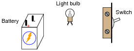
Reveal answer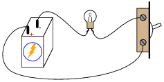
Follow-up question: suppose the circuit were built like this but the light bulb did not turn on when the switch was closed. Identify at least five specific things that could be wrong with the circuit to cause the light not to turn on when it should.
Notes:One of the more difficult skills for students to develop is the ability to translate a nice, neat schematic diagram into a messy, real-world circuit, and visa-versa. Developing this skill requires lots of practice.
In case students have not learned battery symbol convention yet, please point out to them the “ ” and “-” polarity marks, and note which side of the battery is which.
One analogy to use for the switch’s function that makes sense with the schematic is a drawbridge: when the bridge is down (closed), cars may cross; when the bridge is up (open), cars cannot.
-
Question 29 of 41
Shown here is a circuit constructed on a PCB (a “Printed Circuit Board”), with copper “traces” serving as wires to connect the components together:
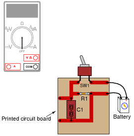
How would the multimeter be used to measure the current through the component labeled “R1” when energized? Include these important points in your answer:
- • The configuration of the multimeter (selector switch position, test lead jacks)
- • The connections of the meter test leads to the circuit
- • The state of the switch on the PCB (open or closed)
Reveal answer
In order to measure current through resistor R1, one of its leads must be de-soldered from the circuit board so that the meter may be connected directly in-line (in series) with it.
Notes:Many multimeters use “international” symbols to label DC and AC selector switch positions. It is important for students to understand what these symbols mean.
As you can see in this answer, measuring current through components is generally more difficult than measuring voltage across components, and involves greater risk because the meter must conduct the component’s full current (which in some cases may be significant). For this reason, technicians need to learn troubleshooting techniques prioritizing voltage measurements over current measurements.
-
Question 30 of 41
Why is it a very bad idea to connect an ammeter directly across a voltage source, like this?
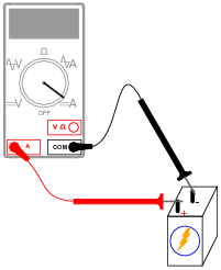
Reveal answerDue to the ammeter’s very low resistance, it will “draw” a lot of current from the voltage source. In effect, the ammeter will form a short circuit with the voltage source, potentially damaging the meter and/or the source.
In applications where the voltage source possesses very little internal resistance of its own, the current surge resulting from such a short-circuit may be huge. Very large surges of electric current are capable of heating wires to the point where their insulation bursts into flames, as well as causing super-heated blasts of plasma (electrically ionized gas) to form at any point of electrical contact where there is a spark. Either of these high-temperature conditions are hazardous to the person holding the meter and test leads!
Notes:An important point to discuss is how electrical safety encompasses more than just shock hazard. In particular, arc blasts caused by high-current “faults” such as this may be just as dangerous as electric shock. At the very least, placing an ammeter directly across the terminals of a voltage source will likely result in the ammeter’s fuse being blown.
In some cases, ammeter fuses are more expensive than one might think. Safety-rated ammeters often use expensive fast-action fuses with significant current interruption ratings. In the case of the Fluke 187 and 189 multimeters, these fuses cost around $8 each (American dollars, 2004)!