Facebook
 Google
 GitHub
 Linkedin
Analog Integrated Circuits
Summer and Subtractor OpAmp Circuits
25 questions By Tony R. Kuphaldt
-
Question 13 of 25
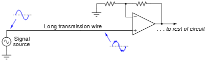
If a weak voltage signal is conveyed from a source to an amplifier, the amplifier may detect more than just the desired signal. Along with the desired signal, external electronic “noise” may be coupled to the transmission wire from AC sources such as power line conductors, radio waves, and other electromagnetic interference sources. Note the two waveshapes, representing voltages along the transmission wire measured with reference to earth ground:
Shielding of the transmission wire is always a good idea in electrically noisy environments, but there is a more elegant solution than simply trying to shield interference from getting to the wire. Instead of using a single-ended amplifier to receive the signal, we can transmit the signal along two wires and use a difference amplifier at the receiving end. Note the four waveforms shown, representing voltages at those points measured with reference to earth ground:
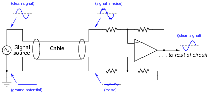
If the two wires are run parallel to each other the whole distance, so as to be exposed to the exact same noise sources along that distance, the noise voltage at the end of the bottom wire will be the same noise voltage as that superimposed on the signal at the end of the top wire.
Explain how the difference amplifier is able to restore the original (clean) signal voltage from the two noise-ridden voltages seen at its inputs with respect to ground, and also how the phrase common-mode voltage applies to this scenario.
Reveal answer“Common-mode” voltage refers to that voltage which is common to two or more wires as measured with reference to a third point (in this case, ground). The amplifier in the second circuit only outputs the difference between the two signals, and as such does not reproduce the (common-mode) noise voltage at its output.
Challenge question: re-draw the original (one wire plus ground) schematic to model the sources of interference and the wire’s impedance, to show exactly how the signal could become mixed with noise from source to amplifier.
Notes:Differential signal transmission is a very practical application of difference amplifiers, and forms the foundation of certain data transmission standard physical layers such as RS-422 and RS-485.
-
Question 14 of 25
Singers who wish to practice singing to popular music find that the following vocal eliminator circuit is useful:
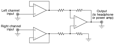
The circuit works on the principle that vocal tracks are usually recorded through a single microphone at the recording studio, and thus are represented equally on each channel of a stereo sound system. This circuit effectively eliminates the vocal track from the song, leaving only the music to be heard through the headphone or speaker.
Explain how the operational amplifiers accomplish this task of vocal track elimination. What role does each opamp play in this circuit?
Reveal answerThe first two opamps merely “buffer” the audio signal inputs so they do not become unnecessarily loaded by the resistors. The third opamp subtracts the left channel signal from the right channel signal, eliminating any sounds common to both channels.
Challenge question: unfortunately, the circuit as shown tends to eliminate bass tones as well as vocals, since the acoustic properties of bass tones make them represented nearly equally on both channels. Determine how the circuit may be expanded to include opamps that re-introduce bass tones to the “vocal-eliminated” output.
Notes:Circuits like this are great for illustration, because they show practical application of a principle while engaging student interest.
One of my students, when faced with the challenge question, suggested placing a high-pass filter before one of the subtractor’s inputs, eliminating bass tones at one of the inputs and therefore reproducing bass tones at the subtractor output. This is a great idea, and shows what can happen when students are given a forum to think creatively and freely express ideas, but there are some practical reasons it would be difficult to implement. The concept works great if we assume the use of a perfect HP filter, with absolutely zero phase shift and zero attenuation through the entire pass-band. Unfortunately, real filter circuits always exhibit some degree of both, and so the process of subtraction would not be as effective as necessary to eliminate the vocals from a song.
-
Question 15 of 25
The following circuit is known as an instrumentation amplifier:

Suppose a DC voltage were to be applied to the non-inverting input terminal, 1 volt at Vin( ), and the inverting input terminal grounded. Complete the following table showing the output voltage of this circuit for different values of m:
m Vout
1
2
3
4
5
6
Reveal answer
m Vout
1 3 volts
2 2 volts
3 1.66 volts
4 1.5 volts
5 1.4 volts
6 1.33 volts
AV(diff) = 2 m mFollow-up question: why did I choose to set the non-inverting input voltage at 1 volts and ground the inverting input? Should we not be able to calculate gain given any two input voltages and a value for m? Explain the purpose behind my choice of input voltage conditions for this “thought experiment.”
Notes:While the relationship between instrumentation amplifier differential gain and m may be looked up in any good opamp circuit textbook, it is something that your students should learn to figure out on their own from the data in the table.