Facebook
 Google
 GitHub
 Linkedin
Discrete Semiconductor Devices and Circuits
Zener Diodes
23 questions By Tony R. Kuphaldt
-
Question 10 of 23
Calculate the current through the zener diode for the given values of load resistance in this circuit:
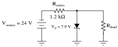
- Rload = 1.5 kΩ ; Izener =
- Rload = 1 kΩ ; Izener =
- Rload = 910 Ω ; Izener =
- Rload = 780 Ω ; Izener =
Reveal answer- Rload = 1.5 kΩ ; Izener = 8.15 mA
- Rload = 1 kΩ ; Izener = 5.52 mA
- Rload = 910 Ω ; Izener = 4.74 mA
- Rload = 780 Ω ; Izener = 3.29 mA
Follow-up question: what value of load resistance will result in zero current through the zener diode (while still maintaining an output voltage of 7.9 volts)?
Notes:This exercise in current calculation is supposed to get students to realize the inverse relationship between load current and zener current: that the zener diode regulates voltage by acting as a parasitic load of varying proportion. Simply put, the diode loads down the circuit as much as needed to maintain a stable voltage at the load terminals.
It should be noted that the calculated answers shown here will not precisely match a real zener diode circuit, due to the fact that zener diodes tend to gradually taper off in current as the applied voltage nears the zener voltage rating rather than current sharply dropping to zero as a simpler model would predict.
The follow-up question is very important. All zener diode regulator circuits have a minimum load resistance value that must be adhered to, lest the output voltage droop below the regulation point. Discuss with your students how the zener diode’s “loading” behavior explains the need for a certain minimum load resistance value.
-
Question 11 of 23
Calculate the current through the zener diode for the given values of load resistance in this circuit:
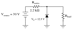
- Rload = 2 kΩ ; Izener =
- Rload = 3 kΩ ; Izener =
- Rload = 4 kΩ ; Izener =
- Rload = 5 kΩ ; Izener =
Reveal answer- Rload = 2 kΩ ; Izener = 1.705 mA
- Rload = 3 kΩ ; Izener = 3.788 mA
- Rload = 4 kΩ ; Izener = 4.830 mA
- Rload = 5 kΩ ; Izener = 5.455 mA
Follow-up question: what value of load resistance will result in zero current through the zener diode (while still maintaining an output voltage of 5.1 volts)?
Notes:This exercise in current calculation is supposed to get students to realize the inverse relationship between load current and zener current: that the zener diode regulates voltage by acting as a parasitic load of varying proportion. Simply put, the diode loads down the circuit as much as needed to maintain a stable voltage at the load terminals.
It should be noted that the calculated answers shown here will not precisely match a real zener diode circuit, due to the fact that zener diodes tend to gradually taper off in current as the applied voltage nears the zener voltage rating rather than current sharply dropping to zero as a simpler model would predict.
The follow-up question is very important. All zener diode regulator circuits have a minimum load resistance value that must be adhered to, lest the output voltage droop below the regulation point. Discuss with your students how the zener diode’s “loading” behavior explains the need for a certain minimum load resistance value.
-
Question 12 of 23
Calculate the power dissipated by the 5-volt zener diode for the following values of motor current (assume the battery voltage remains constant at 12 volts):
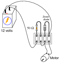
- Imotor = 20 mA ; Pzener =
- Imotor = 50 mA ; Pzener =
- Imotor = 90 mA ; Pzener =
- Imotor = 120 mA ; Pzener =
- Imotor = 150 mA ; Pzener =
Reveal answer- Imotor = 20 mA ; Pzener = 600 mW
- Imotor = 50 mA ; Pzener = 450 mW
- Imotor = 90 mA ; Pzener = 250 mW
- Imotor = 120 mA ; Pzener = 100 mW
- Imotor = 150 mA ; Pzener = 0 mW
Follow-up question: is load voltage maintained at 5 volts constant throughout this range of load currents (from 20 mA to 150 mA)?
Notes:The follow-up question is fairly important here, as students need to realize the limitations of zener-based voltage regulators. Most importantly, are they able to calculate the exact current limit of a zener-based voltage regulator - the point at which it stops regulating?
It should be noted that the calculated answers shown here will not precisely match a real zener diode circuit, due to the fact that zener diodes tend to gradually taper off in current as the applied voltage nears the zener voltage rating rather than current sharply dropping to zero as a simpler model would predict.