Facebook
 Google
 GitHub
 Linkedin
Discrete Semiconductor Devices and Circuits
Zener Diodes
23 questions By Tony R. Kuphaldt
-
Question 7 of 23
Suppose you had the boring job of manually maintaining the output voltage of a DC generator constant. Your one and only control over voltage is the setting of a rheostat:
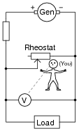
What would you have to do to maintain the load voltage constant if the load resistance changed so as to draw more current? Being that your only control over load voltage is the adjustment of a variable resistance in parallel with the load, what does this imply about the generator’s output voltage (directly across the generator terminals), compared to the target load voltage?
Reveal answerIn order to increase the load voltage, you must increase the resistance of the rheostat. In order for this scheme to work, the generator’s voltage must be greater than the target load voltage.
Note: this general voltage control scheme is known as shunt regulation, where a parallel (shunt) resistance is varied to control voltage to a load.
Follow-up question: assuming the load voltage is maintained at a constant value by an astute rheostat operator despite fluctuations in load current, how would you characterize the current through the generator’s windings? Does it increase with load current, decrease with load current, or remain the same? Why?
Notes:The direction of rheostat adjustment should be obvious, as is the fact that the generator’s voltage must be at least as high as the intended (target) load voltage. However, it may not be obvious to all that the generator’s voltage cannot merely be equal to the intended load voltage.
To illustrate the necessity of this, ask your students how the system would work if the generator’s output voltage was exactly equal to the intended load voltage. Emphasize the fact that the generator is not perfect: it has its own internal resistance, the value of which cannot be changed by you. What position would the rheostat have to be in, under these conditions, in order to maintain target voltage at the load? Could the target voltage be maintained at all?
A helpful analogy for students is that of a car with an automatic transmission, with its speed being controlled by the brake pedal while the accelerator pedal is maintained at a constant position. This is not the most energy-efficient method of speed control, but it will work within certain limits!
-
Question 8 of 23
Describe how a zener diode is able to maintain regulated (nearly constant) voltage across the load, despite changes in load current:

Reveal answerThe zener draws more or less current as necessary from the generator (through the series resistor) to maintain voltage at a nearly constant value.
Follow-up question #1: if the generator happens to output some ripple voltage (as all electromechanical DC generators do), will any of that ripple voltage appear at the load, after passing through the zener diode voltage regulator circuit?
Follow-up question #2: would you classify the zener diode in this circuit as a series voltage regulator or a shunt voltage regulator? Explain your answer.
Challenge question: at what point is the zener diode unable to regulate load voltage? Is there some critical load condition at which the diode ceases to regulate voltage?
Notes:Ask your students to describe how energy-efficient they think this circuit is. Do they suspect it would be more suitable for low-current applications or high-current applications?
-
Question 9 of 23
Calculate the current through the zener diode for the given values of load resistance in this circuit:
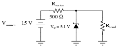
- Rload = 1 kΩ ; Izener =
- Rload = 910 Ω ; Izener =
- Rload = 680 Ω ; Izener =
- Rload = 470 Ω ; Izener =
- Rload = 330 Ω ; Izener =
Do you see any relationship between load current and zener diode current? If so, explain what that relationship is.
Reveal answerAs the load current increases (with less load resistance), zener diode current decreases:
- Rload = 1 kΩ ; Izener = 14.7 mA
- Rload = 910 Ω ; Izener = 14.2 mA
- Rload = 680 Ω ; Izener = 12.3 mA
- Rload = 470 Ω ; Izener = 8.95 mA
- Rload = 330 Ω ; Izener = 4.35 mA
Follow-up question: what value of load resistance will result in zero current through the zener diode (while still maintaining an output voltage of 5.1 volts)?
Notes:This exercise in current calculation is supposed to get students to realize the inverse relationship between load current and zener current: that the zener diode regulates voltage by acting as a parasitic load of varying proportion. Simply put, the diode loads down the circuit as much as needed to maintain a stable voltage at the load terminals.
It should be noted that the calculated answers shown here will not precisely match a real zener diode circuit, due to the fact that zener diodes tend to gradually taper off in current as the applied voltage nears the zener voltage rating rather than current sharply dropping to zero as a simpler model would predict.
The follow-up question is very important. All zener diode regulator circuits have a minimum load resistance value that must be adhered to, lest the output voltage droop below the regulation point. Discuss with your students how the zener diode’s “loading” behavior explains the need for a certain minimum load resistance value.