
 Facebook
 Google
 GitHub
 Linkedin
AC Electric Circuits
Advanced Electromagnetism and Electromagnetic Induction
11 questions By Tony R. Kuphaldt
-
Question 10 of 11
It is a known fact that the nonlinearity of a ferromagnetic material’s B-H curve will cause an inductor’s current to be non-sinusoidal, even when the voltage impressed across the inductor is perfectly sinusoidal:
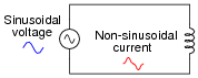
Unless coil resistance is substantial, the core flux waveform (φ) over time will be just as sinusoidal as the voltage waveform, because without resistance to drop voltage, the relationship between voltage and flux is e = N[(dφ)/dt], the rate-of-change of a perfect sine wave being a perfect cosine wave.
Knowing that the core flux waveform will be sinusoidal allows us to derive the inductor current waveform from the B-H curve using a graphical “trick”: using the B-H curve to correlate instantaneous values of flux over time with instantaneous values of coil current over time. When used in this manner, the B-H curve is called a transfer characteristic, because it is used as a map to “transfer” points on one waveform to points on another waveform. We know that φ is directly proportional to B because B = [(Φ)/A], and the core area is constant. We also know that i is directly proportional to H, because
F = NI and H = [(F)/l], and both the core length and the number of turns of wire are constant:
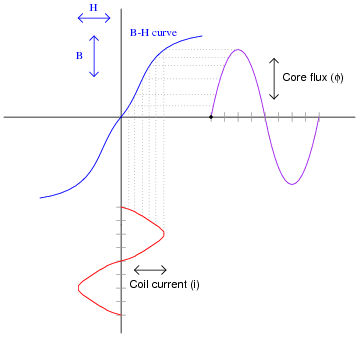
Notice that the flux waveform is nice and sinusoidal, while the current waveform is not.
Based on what you see here, describe how an inductor designer can minimize the current distortion in an inductor. What conditions make this distortion better, and what conditions make it worse?
Reveal answerThe key to minimizing current distortion is to keep the core flux amplitudes within the straightest portions of the core’s B-H curve. Anything that causes the flux to reach greater amplitudes, and get closer to the “saturated” portion of the B-H curve, will create more distortion of the current waveform.
Notes:I wrote this question for the purpose of introducing students to a technique commonly found in older textbooks, but not found in newer textbooks quite as often: graphically generating a plot by the comparison of one waveform against a static function, in this case the comparison of the flux waveform against the B-H curve. Not only is this technique helpful in analyzing magnetic nonlinearities, but it also works well to analyze semiconductor circuit nonlinearities.
-
Question 11 of 11
∫f(x) dx Calculus alert!
Faraday’s Law of electromagnetic induction states that the induced voltage across a coil of wire is equal to the number of “turns” in the coil multiplied by the rate of change of magnetic flux over time:v = N dφ dtOften you will see a negative sign preceding the right-hand side of the equation, to properly denote polarity of the induced voltage. This is the mathematical expression of Lenz’s Law. In this equation, though, the negative sign is omitted and we pay attention only to the absolute value of induced voltage.
Use calculus techniques to express φ as a function of v, so that we may have an equation useful for predicting the amount of magnetic flux accumulated in an inductor or transformer given the voltage across it (v) and the time of the accumulation (T). Hint: you may treat this as a differential equation with separable variables.
For those who are unfamiliar with calculus, you may still answer this question, albeit in a simpler form: write an equation describing the change in magnetic flux within a coil (∆Φ) given a constant DC voltage across the coil (V) and a certain amount of time (t).
Reveal answerφ = 1 N⌠ ⌡ T 0 v dt If the voltage is constant (V), the change in flux may be calculated by this simple equation:
∆Φ = V t NNotes:Even if students are not familiar with differential equations at all, they should be able to arrive at the second (algebraic) equation if they properly understand how flux rate-of-change relates to induced voltage.






Question 5 - If the source voltage polarity is reversed, would the decay of the field respond quicker than if the source voltage was simply turned off? In other words, would the slope of the flux decay/growth be steeper at voltage reversal, than what it is at its initial condition when the voltage is first applied?