Facebook
 Google
 GitHub
 Linkedin
Discrete Semiconductor Devices and Circuits
Clipper and Clamper Circuits
21 questions By Tony R. Kuphaldt
-
Question 19 of 21
Draw the output waveform shape for this circuit, assuming an ideal diode (no forward voltage drop and no reverse leakage):

Reveal answer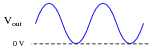
Follow-up question: how does the clamper circuit “know” how much it needs to bias the AC voltage waveform so that it gets shifted just enough to eliminate reversals of polarity? Would this circuit function the same if the AC voltage were increased or decreased? Explain why.
Notes:Ask your students to replace the capacitor with a DC voltage source (oriented in the correct polarity, of course), and explain how the capacitor actually functions as a voltage bias in this clamper circuit.
-
Question 20 of 21
Design a clamper circuit that biases the AC waveform so it lies completely below (negative) the zero line:
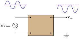
Reveal answer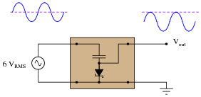
Notes:Have multiple students share their thoughts as to how they designed the clamper circuit.
-
Question 21 of 21
In this circuit, the values of capacitor C1 and resistor R1 are chosen to provide a short time constant, so they act as a differentiator network. This results in a brief pulse of voltage across R1 at each leading edge of the square wave input. Capacitor C2 and resistor R2 are sized to provide a long time constant, so as to form an integrator network. This time-averages the brief pulses into a final DC output voltage relatively free of ripple.
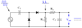
Explain what happens to the output voltage as the input frequency is increased, assuming the input voltage amplitude does not change. Can you think of any practical applications for a circuit such as this?
Reveal answerThe DC output voltage will increase as the input signal frequency is increased. This lends itself to frequency measurement applications.
Notes:Do not accept an answer from students along the lines of “frequency measurement.” Ask them to provide some practical examples of systems where frequency measurement is important. If they have difficulty thinking of anything practical, suggest that the input (square wave) signal might come from a sensor detecting shaft rotation (one pulse per revolution), then ask them to think of possible applications for a circuit such as this.