Facebook
 Google
 GitHub
 Linkedin
Digital Circuits
High-Reliability Circuits
9 questions By Tony R. Kuphaldt
-
Question 7 of 9
The Orbiting Astronomical Observatory was a NASA project during the late 1960’s and 1970’s to place precision observational instruments in earth orbit for scientific purposes. Satellites designed for this program had to have “hardened” circuitry to withstand the radiation, extreme temperatures, and other harsh conditions of space.
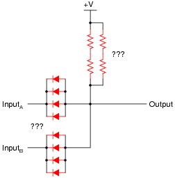
An example of some of this “fail-safe” circuitry is shown here: a passive, quad-redundant, two-input AND gate:

First, draw a schematic for a non-redundant, passive AND gate. Which components shown in the above schematic are “redundant,” and which are essential?
Then, explain why the circuit is referred to as quad-redundant. How many individual component failures, minimum, must occur before the gate’s functionality is compromised? Prove your answer through an analysis of the circuit’s operation.
Reveal answerThis is the schematic for a non-redundant, passive AND gate:

Follow-up question: why do you suppose transistors were eliminated from this gate circuit’s design?
Challenge question: note that there are series-parallel clusters of four diodes in the quad-redundant gate circuit, where there only needs to be one for minimum functionality. Note also that the four resistors are all in parallel, not in a series-parallel arrangement. Why is this? Why not cluster all four diodes in parallel instead of series-parallel? Why not cluster the four resistors in series-parallel, instead of simple parallel?
Notes:It is worth discussing with your students how a passive gate such as this functions at all. Ask your students whether this gate requires the input signals to be current-sourcing or current-sinking, and whether or not the passive nature of the circuit constitutes a problem interfacing it with other logic circuits.
The challenge question is a very good one to discuss in class with all your students. The answer to why the diodes are in a series-parallel arrangement should be fairly easy to understand. Why the resistors can be simply paralleled is a bit more complex to answer. The key to understanding both these design features lies in the typical failure modes of each component type.
-
Question 8 of 9
One use for “rectifying” diodes is to parallel multiple power supplies for extra reliability in powering a critical system:
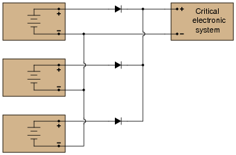
However, as an experienced electronics technician, you should know that diodes are not immune to failure. Modify this schematic diagram to include three extra (redundant) diodes that will allow normal operation if any one of the three original diodes were to fail, assuming the most common failure mode of rectifier-type diodes.
Reveal answerThe best way to wire pairs of rectifying diodes together for redundancy is in series:
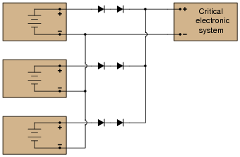
Notes:While this may seem like “overkill,” to use redundant diodes on redundant power supplies, it is a design feature that does not cost very much. Given the measurable improvement in reliability with minimal increase in cost, this design feature is not unreasonable.
-
Question 9 of 9
The Orbiting Astronomical Observatory was a NASA project during the late 1960’s and 1970’s to place precision observational instruments in earth orbit for scientific purposes. Satellites designed for this program had to have “hardened” circuitry to withstand the radiation, extreme temperatures, and other harsh conditions of space.
An example of some of this “fail-safe” circuitry is shown here: a quad-redundant inverter (NOT) gate:
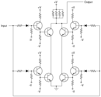
Explain why the circuit is referred to as quad-redundant. How many individual component failures, minimum, must occur before the gate’s functionality is compromised? Prove your answer through an analysis of the circuit’s operation.
Reveal answerIf you analyze this circuit carefully, you will find that it may actually fail with just two component faults, if they are the right type of fault, in the right locations!
Notes:This circuit is a good one to discuss with your students in class. Ask them to explain its basic operation: if all components are functioning properly, what happens when it receives a “high” input, versus a “low” input? Do the input signals need to be current-sourcing or current-sinking? What about the output of this circuit: does it source or sink current?