 Facebook
 Google
 GitHub
 Linkedin
Introduction to Modulation Techniques in RF Systems
In this article, we discuss the basics of RF modulation and how it affects the performance of communication systems.
Modulation is essential not only for communication systems—including radio broadcasts, satellite links, and mobile networks—but also for the effective operation of radar, radio navigation, and similar technologies. However, grasping its intricacies can be a daunting task. A vast array of modulation techniques exists today, each with its own unique properties and complexities.
At a minimum, RF engineers should possess a solid understanding of the basic principles of modulation theory. In this article, we’ll embark on a journey to unravel these principles and build an understanding of modulation’s critical role in communication systems. We’ll begin by defining modulation and examining how it fits into the process of signal transmission, then move on to discuss how the choice of modulation scheme influences system performance.
What Is Modulation?
Say that we’re transmitting auditory information like speech or music via a radio system. The audio spectrum consists of frequency components ranging from 20 Hz to 20 kHz. However, the spectrum of a real signal is symmetric around zero frequency, so we consider our signal to be centered at the origin (f = 0).
This is what we call a baseband signal, meaning a band-limited signal centered at f = 0. Modulation is the process by which we convert a baseband signal into a passband signal, which is centered around a non-zero carrier frequency (fc). Figure 1(a) displays an example baseband spectrum; Figure 1(b) shows how modulation shifts the baseband spectrum by ±fc.
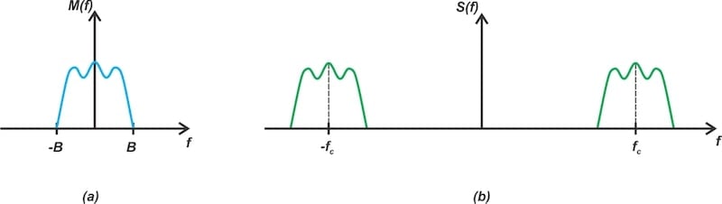
Figure 1. The spectrum of the baseband signal (a) and the modulated wave (b).
You could also think of modulation as the process of transferring the information content of a baseband signal to an RF carrier before transmission. While it’s technically possible to directly transmit a baseband signal through a radio channel, transforming it into a passband signal first is usually much more effective.
There are many different ways of modulating a signal. Perhaps the most straightforward technique is amplitude modulation, which is illustrated in Figure 2.

Figure 2. An example baseband signal in the time domain (top) and its corresponding amplitude-modulated signal (bottom).
In this example, a relatively slowly varying baseband signal (m(t)) is changed into a rapidly varying modulated signal (s(t)) whose amplitude changes in accordance with the amplitude of m(t).
We now have a basic idea of what modulation is. However, a crucial question remains: if it’s possible to transmit an unmodulated signal, what makes modulation necessary? To answer this, let’s start by examining how a signal passes through a typical communication system. This will help us place our discussion of modulation in its larger context.
A Simplified Communication System
Consider the heterodyne transmitter and receiver system in Figure 3.
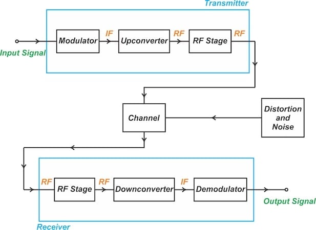
Figure 3. Simplified block diagram of a heterodyne transmitter and receiver system.
In this diagram, the input signal is the baseband signal we’ve decided to transmit. The overall function of the transmitter is to modify the baseband signal for efficient transmission. The receiver’s role is to extract the baseband data from the modulated carrier signal it receives.
Let’s follow the input signal through the system, starting from when it enters the transmitter.
- The baseband signal is fed into a modulator, which modulates the amplitude, frequency, or phase of an intermediate-frequency (IF) signal.
- The upconverter translates the modulator’s output to an RF carrier frequency.
- The RF signal enters the transmitter’s RF stage, which includes filters, matching networks, and a power amplifier. The goal of the RF stage is to ensure the delivery of maximum power to the antenna. It also filters out any out-of-band frequency components that arise due to the nonlinearity of practical components and circuits.
- The signal leaves the transmitter and enters the channel, which is simply the physical medium that conveys signals from the transmitter to the receiver. In the context of a wireless connection, the channel is the air itself.
- At the other end of the channel, the RF stage within the receiver employs an antenna to capture the high-frequency signal. Typically, it will then use a low-noise amplifier to amplify the signal.
- The downconverter translates the amplified signal to an IF frequency.
- The demodulator retrieves the original baseband signal from the modulated wave. In voice radio, this means extracting the original voice signal.
Note that demodulation is essentially the reverse of modulation. Modulation involves embedding the information into a carrier wave. Demodulation extracts the information from the carrier.
Communication Hurdles: Attenuation, Noise and Distortion
As you may have noticed, there’s a block in the above diagram we haven’t mentioned—the one connected to the channel and labeled “Distortion and Noise.”
Because it acts as a natural filter, the channel can attenuate and distort the signal during its propagation. The signal attenuation increases with the distance between the transmitter and receiver. Meanwhile, the signal undergoes distortion due to phenomena such as:
- Frequency-dependent gains.
- Multipath effects.
- Doppler shift.
Furthermore, the signal encounters interference from random noise sources as it traverses the channel. These noise sources include:
- Electrical contact switches.
- Automobile ignition systems.
- Cell phone emissions.
- Microwave ovens.
- Lightning and other atmospheric disturbances.
Finally, noise isn’t only introduced as the signal propagates through the channel. It’s also produced inside the electrical circuits of the transmitter and receiver, primarily due to the random motion of charged particles in conductors.
These imperfections make signal transmission challenging. Fortunately, modulation theory can help—for a given signal attenuation and noise level, the choice of modulation technique is a key determinant in the performance of the transmitter-receiver system. Let’s explore this further in the next section.
Modulation Method Affects Data Rate
There is a theoretical limit to the amount of information that can be transmitted over a communication channel for a given bandwidth (B) and signal-to-noise ratio (SNR). This limit, known as the channel capacity or Shannon limit, is given by:
$$C ~=~ B ~\times~ \log_2 (SNR~+~1)$$
By providing us with the maximum possible data rate for error-free communication, Shannon’s channel capacity equation serves as a benchmark for the efficiency of modulation techniques. Shannon doesn’t show how to achieve this theoretical limit, but he does prove it’s possible. Engineers therefore strive to design modulation methods that allow us to approach the Shannon limit.
But how does the choice of modulation technique affect data rate? To better understand this, consider the hypothetical modulated wave in Figure 4. In this modulation method, the amplitude of the carrier takes four distinct levels ( A1, A2, A3, and A4) based on the state of a two-bit input signal.
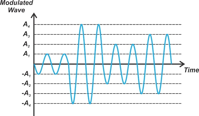
Figure 4. Example of four-level amplitude modulation.
Increasing the number of carrier amplitude levels allows us to transmit more information through the same channel bandwidth. For instance, utilizing eight distinct amplitude levels allows each level to encode three bits.
The downside of this technique is that a greater number of levels means less separation between them, rendering the system more vulnerable to noise interference. For that reason, increasing the number of levels is only an effective way of boosting the data transmission rate if we have a high signal-to-noise ratio. The system’s noise level must be low enough to prevent erroneous amplitude detection at the receiver.
Since the amplitude and phase of the carrier wave represent two separate degrees of freedom, we can further enhance the information throughput by changing the phase as well as the amplitude of the carrier. These two degrees of freedom represent orthogonal bases for a two-dimensional space. The constellation of the transmitted symbols can therefore be represented by points on a plane, as in Figure 5.
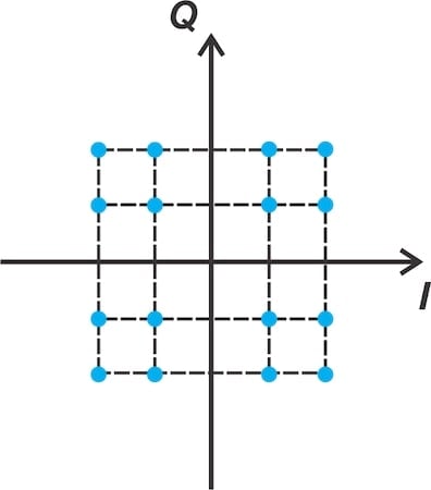
Figure 5. The combination of amplitude and phase represented as a constellation of points on a plane.
From this, it’s apparent that the data rate depends on how we modulate the carrier wave.
Other Benefits of Using an RF Carrier Wave
In addition to improving the data rate, employing an RF carrier signal for data transmission enables precise control of the radiated frequency spectrum. It also allows us to utilize the RF bandwidth more efficiently. By using different carrier frequencies, we can implement a frequency-division multiplexing system that allows for the simultaneous transmission of signals from multiple message sources.
Furthermore, transmitting signals at low frequencies requires large antennas. Using an RF carrier therefore simplifies the transmitter and receiver structure.
Wrapping Up
Different modulation schemes yield varying performance levels when subjected to the same degree of channel attenuation and receiver noise. Given the limited availability of the electromagnetic spectrum, it’s preferable to select a modulation scheme that utilizes the spectrum efficiently. An efficient modulation scheme uses a narrower bandwidth for a given information rate.
The choice of modulation scheme also influences the selection of power amplifiers in the transmitter design. Certain modulation techniques permit the use of nonlinear power amplifiers, which are notably more efficient in terms of power consumption. A trade-off exists between the detectability of the received signal, the efficiency in using the available spectrum, and the efficiency of the power amplifiers.
This article is Part 1 of a series on amplitude modulation in RF systems. A complete list of articles in this series is provided below:
- Introduction to Modulation Techniques in RF Systems
- Understanding Double-Sideband Suppressed-Carrier Modulation
- Understanding Conventional Amplitude Modulation
- Understanding the Square-Law Modulator for Generating AM Signals
- Introduction to the Balanced Modulator for AM Signals
- How Do Switching Modulators Generate AM Signals?
- Understanding How Ring Modulators Produce AM Signals
- Four Interesting AM Modulation Circuits You Should Know About
- Demodulating Double-Sideband AM Signals
- Introduction to Single-Sideband Modulation: The Filter Method
- The Phasing Method and Hilbert Transforms for Single-Sideband Modulation
- A Visual Approach to Understanding the Phasing Method for SSB Modulation
- How Phasors Help Us Understand Bandpass Signals
- Introduction to Weaver’s Method for SSB Signal Generation
- Exploring the Operation of the Weaver Modulator for Single-Sideband Modulation
All images used courtesy of Steve Arar
Related Content


Hello, designing PWM using analog/OpAmps with 5-12 Volts output. It would be useful if suggested some typical schematics to generate a square wave and triangular wave generator.